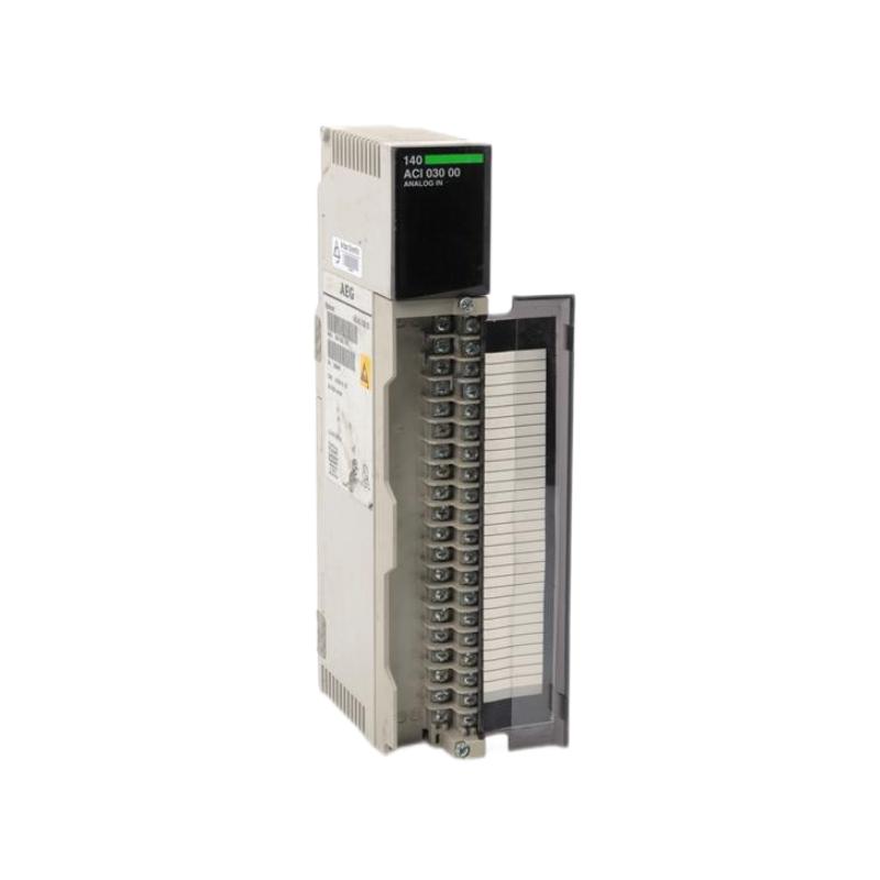
Schneider 140ACI03000 Fault Troubleshooting Guide (Signal Drift, Noise & Channel Failure)
Schneider 140ACI03000 faults are often misdiagnosed as transmitter failure. Field evidence shows most issues originate from wiring errors, grounding problems, or EMI interference, not module defects.
Fault Symptoms in Field Operation
- Unstable analog readings (jittering values)
- Sudden jumps to full scale or zero
- One channel stuck at fixed value
- Slow response or delayed signal update
- Inconsistent readings between identical sensors
In one refinery case, a flow signal oscillated between 30% and 80% despite stable process conditions.
Field Diagnostic Approach
1. Loop Current Verification
- Measure actual mA using loop calibrator
- Compare with PLC raw input value
- Check for broken wire detection (4–20 mA fault mode)
A mismatch indicates wiring or scaling issue, not module failure.
2. Ground Loop Analysis
- Check shield termination points
- Verify no dual grounding exists
- Measure potential difference between sensor and cabinet ground
Ground loops often introduce low-frequency signal drift.
3. Channel Isolation Check
- Swap input channels to isolate fault
- If problem follows channel → wiring issue
- If problem stays → configuration or module issue
Common Failure Modes
Ground Loop Interference (Most Frequent)
- Symptoms: drifting or noisy signal
- Fix: single-point grounding, isolate shields
Incorrect Signal Type Configuration
- Symptoms: saturation at high/low range
- Fix: match 4–20 mA vs 1–5 V setting
EMI Coupling from Power Cables
- Symptoms: spikes during motor start
- Fix: reroute cables, improve shielding
Field Recovery Case Study
Scenario: Reactor temperature reading fluctuating unpredictably.
Diagnosis:
- Sensor output stable (verified 12.8 mA constant)
- PLC reading oscillating between 40–90%
- Shield grounded at both ends
Corrective Actions:
- Removed secondary grounding point
- Re-routed analog cable away from VFD panel
- Re-terminated shield at cabinet only
Result:
Signal stabilized within ±0.2% full scale, process control restored.