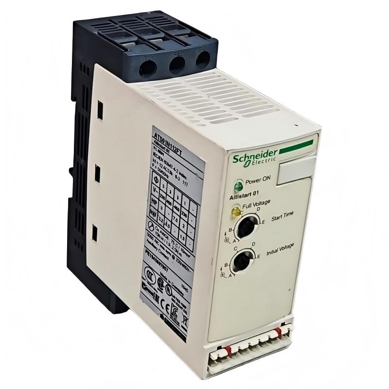
Schneider ATS01N112FT Soft Starter Installation Guide for Small Motor Control Systems
Schneider ATS01N112FT soft starter installation issues are most commonly caused by incorrect load sizing, improper 3-phase wiring, or wrong control voltage configuration, rather than internal thyristor failure. The ATS01 series is designed for simple machine applications, where smooth starting and basic motor protection are required for pumps, fans, conveyors, and compressors.
Schneider ATS01N112FT Role in Motor Control Architecture
The Schneider ATS01N112FT belongs to the Altistart 01 (ATS01) soft starter family, designed for compact and cost-efficient motor starting control.
Key functions:
- Voltage ramp soft start / soft stop
- Reduction of inrush current during motor start
- Mechanical stress reduction on drive systems
- Integrated bypass for heat reduction after startup
- Basic protection against phase loss and abnormal start conditions
Technical characteristics confirmed from manufacturer data:
- Rated current: 12 A
- Supply voltage: 110–480 V AC
- Motor power: up to 5.5 kW (3-phase 400 V)
- Control voltage: 24 V AC/DC or 110 V AC depending on variant
- Start method: voltage ramp with adjustable acceleration time
Field application: In one HVAC fan system, replacing direct-on-line (DOL) starting with ATS01 reduced mechanical coupling wear and eliminated repeated belt slippage failures during startup.
Installation Conditions (Critical Engineering Requirements)
1. Power Circuit Wiring Integrity (Most Common Issue Area)
- Ensure correct L1 / L2 / L3 phase sequence
- Verify tight terminal torque on input and output
- Confirm motor insulation is suitable for reduced-voltage starting
- Do not bypass soft starter unless external bypass contactor is correctly designed
Field case: A conveyor system repeatedly tripped due to reversed phase sequence, causing unstable torque during ramp-up and triggering overload protection.
2. Control Voltage Stability
- Control supply must remain stable during start command
- Avoid shared 24V supply with solenoids or relay-heavy loads
- Verify correct control terminal configuration (AC/DC variant dependent)
Field observation: In packaging machines, control voltage dip during multiple simultaneous starts caused random “no start response” events.
3. Load Matching (Critical for ATS01 Series)
ATS01 is designed for simple machines only, meaning:
- Not suitable for heavy cyclic loads with frequent starts
- Not designed for high inertia loads without tuning
- Limited thermal capacity compared to ATS48 / ATS130 series
A mismatch between motor load and soft starter sizing often leads to:
- Overheating
- Start timeout
- Unexpected trip during acceleration
Installation Procedure (Field Engineering Practice)
Step 1: Mechanical Mounting
- Install on DIN rail or panel backplate
- Ensure vertical orientation for cooling
- Maintain clearance for airflow around heatsink
Step 2: Power Wiring
- Connect L1/L2/L3 input from supply
- Connect T1/T2/T3 output to motor terminals
- Verify correct grounding connection
- Tighten all terminals to recommended torque
Step 3: Control Wiring
- Apply start/stop command via PLC or pushbutton
- Verify correct control voltage type (24V AC/DC or 110V AC)
- Ensure no floating control inputs
Step 4: Parameter Setup
- Set motor rated current close to nameplate value
- Adjust ramp time (typically 5–15 seconds for pumps/fans)
- Configure initial torque (avoid too low setting for high inertia loads)
Commissioning Strategy (Engineering Logic)
Step 1: No-Load Start Test
- Run motor without mechanical load
- Confirm smooth acceleration curve
- Ensure no sudden current spikes
Step 2: Loaded Start Validation
- Apply real system load
- Monitor current reduction compared to DOL start
- Verify mechanical stress reduction on coupling/belt
Step 3: Thermal Stability Check
- Perform multiple start cycles
- Monitor heatsink temperature rise
- Ensure starts-per-hour remain within design limits
In one ventilation system, repeated starts without cooling interval caused thermal protection triggering despite correct wiring.