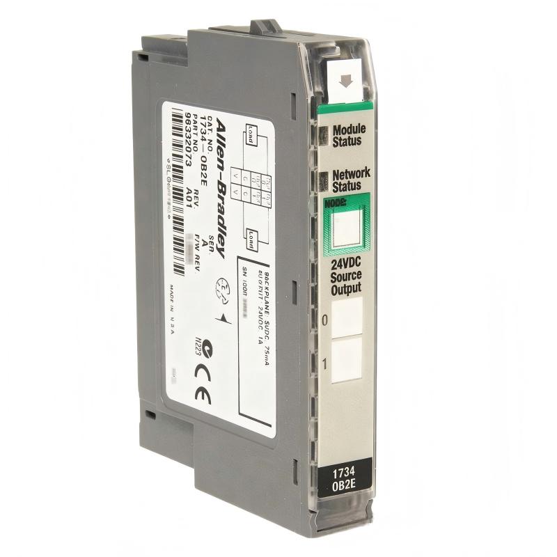
Allen-Bradley 1734-OB2E Point I/O Digital Output Fault Troubleshooting Guide (Fault Diagnosis & Repair)
Allen-Bradley 1734-OB2E output faults are often caused by external field conditions such as short circuits, overloaded actuators, or unstable 24V DC supplies rather than internal module failure. In industrial troubleshooting, replacing the Point I/O module without analyzing the load circuit frequently results in repeated failures.
This article describes a field case involving a 1734-OB2E channel overload fault that caused a machine actuator to stop unexpectedly.
Allen-Bradley 1734-OB2E Point I/O Fault Symptoms During Production Operation
A robotic assembly line reported:
- Pneumatic valve stopped activating
- PLC sequence remained active
- Output indicator showed abnormal condition
- Machine recovered after power reset
Initial observations:
- Network communication normal
- Controller RUN status normal
- Other Point I/O modules operating correctly
The maintenance team suspected a failed digital output module.
However, fault diagnosis required checking the complete output circuit.
Allen-Bradley 1734-OB2E Output Fault Diagnosis Using Field Measurements
The troubleshooting process followed this signal path:
PLC Logic
   ↓
Output Tag
   ↓
1734-OB2E Channel
   ↓
Field Wiring
   ↓
Actuator Coil
Engineers checked each section.
PLC Logic Verification
Result:
- Output command changed correctly
- Program sequence normal
Conclusion:
The problem was not PLC logic.
Output Channel Measurement
Measured:
Normal channel:
- Voltage: 24.2V DC
- Current: 0.38A
Fault channel:
- Voltage dropped after activation
- Current spike exceeded normal range
This indicated a field-side electrical problem.
Allen-Bradley 1734-OB2E Short Circuit Fault Root Cause Analysis
The final root cause was a damaged solenoid valve cable.
Field findings:
- Cable insulation worn through
- Intermittent short to machine frame
- Failure occurred only during robot movement
Failure pattern:
Normal condition:
- Valve current: 0.4A
During cable movement:
- Current spike: >1A
- Output protection activated
The electronic protection function prevented permanent damage to the module.
Allen-Bradley 1734-OB2E Repair Procedure and System Recovery
The corrective action included:
Field Cable Replacement
Old condition:
- Damaged insulation
- Poor cable routing near moving mechanism
Repair:
- Installed flexible industrial cable
- Added mechanical protection sleeve
Output Verification
After repair:
- Output voltage: 24.1V DC
- Coil current: 0.39A
- No diagnostic alarms
Production testing:
- 8-hour continuous operation
- 0 output trips recorded
Allen-Bradley 1734-OB2E Troubleshooting Strategy for Future Failures
For recurring output faults, engineers should check:
1. Load Current Analysis
Measure:
- Normal operating current
- Startup current
- Short circuit behavior
2. Wiring Inspection
Look for:
- Damaged insulation
- Loose terminal connections
- Incorrect polarity
3. Power Supply Stability
Verify:
- 24V DC supply ripple
- Voltage drop during actuator activation
A practical field rule:
“When a 1734-OB2E channel fails, diagnose the load before replacing the module.”
Allen-Bradley 1734-OB2E Long-Term Reliability and Maintenance Recommendations
For reliable Point I/O operation:
- Record output current during commissioning
- Label every field cable clearly
- Monitor module diagnostic information
- Inspect moving machine cables periodically
In real industrial environments, most Allen-Bradley 1734-OB2E Fault Diagnosis cases are solved by tracing the electrical path from controller output to field actuator rather than replacing the I/O hardware.
The fastest troubleshooting method is always:
Logic verification → Output measurement → Wiring inspection → Load analysis → Repair confirmation.