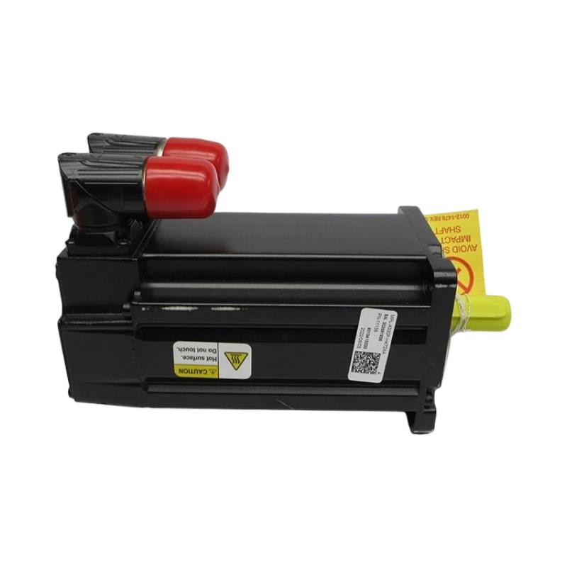
Allen-Bradley MPL-A420P-HK72AA Servo Motor Installation Guide (Wiring & Commissioning)
Allen-Bradley MPL-A420P-HK72AA servo motor installation problems are commonly caused by incorrect motor feedback wiring, incompatible drive configuration, improper grounding, or mechanical alignment errors rather than a failed motor. For a Kinetix motion system, successful commissioning requires the motor, servo drive, feedback circuit, power connections, and mechanical load to be treated as one system.
The Allen-Bradley MPL-A420P-HK72AA servo motor is part of the Allen-Bradley MP-Series low-inertia servo motor family and is intended for precision motion applications where controlled acceleration, positioning, and repeatable torque are required.
Allen-Bradley MPL-A420P-HK72AA Servo Motor Application and Motion System Role
A typical motion system is arranged as follows:
PLC / Motion Controller
        |
        |
Kinetix Servo Drive
        |
        +--------------------+
        |                    |
Motor Power             Feedback
        |                    |
        v                    v
Allen-Bradley MPL-A420P-HK72AA
        |
        |
Mechanical Load
Typical applications include:
- Packaging machinery
- Material handling
- Automated assembly
- Printing equipment
- Pick-and-place machines
- Precision positioning systems
The servo motor should not be commissioned independently from the drive.
The engineering relationship is:
Motor → Drive → Feedback → Motion Controller → Mechanical Load
If one element is incorrectly configured, the resulting symptom can look like a motor fault.
Allen-Bradley MPL-A420P-HK72AA Installation Preparation
Before mounting the motor, engineers should verify:
- Motor model and nameplate information
- Compatible servo drive
- Motor power cable
- Feedback cable
- Brake requirements where applicable
- Shaft and coupling dimensions
- Mechanical load requirements
The installation environment should also be checked for:
- Excessive vibration
- Contamination
- High ambient temperature
- Poor cable routing
- Mechanical misalignment
A servo motor can operate electrically while still suffering from a mechanical installation problem.
For this reason, commissioning should include both electrical and mechanical checks.
Allen-Bradley MPL-A420P-HK72AA Servo Motor Mechanical Installation
Mechanical alignment is particularly important for precision motion.
Check:
- Motor mounting surface
- Shaft alignment
- Coupling condition
- Fastener security
- Load inertia
- Axial and radial loading
Avoid using the motor shaft to force an incorrectly aligned coupling into position.
During one machine commissioning case, an MPL-series servo motor repeatedly generated excessive following error during acceleration.
Initial electrical checks showed:
- Drive power: Normal
- Feedback: Normal
- Motor temperature: Normal
- Encoder communication: Stable
The engineering team then disconnected the mechanical load and performed a low-speed motor test.
The motor operated normally without the load.
Further inspection found that the coupling alignment was incorrect.
After correcting the alignment:
- Following error decreased substantially
- Acceleration became smoother
- Servo operation became stable
The original problem was mechanical rather than electronic.
Allen-Bradley MPL-A420P-HK72AA Motor Power and Feedback Wiring
Servo motor wiring should be checked carefully before energizing the system.
Verify:
- Motor power phases
- Protective grounding
- Feedback connection
- Cable shielding
- Connector seating
A simplified architecture is:
Servo Drive
    |
    +---- Motor Power Cable ----> MPL-A420P-HK72AA
    |
    +---- Feedback Cable -------> Motor Feedback Device
Do not treat the feedback cable as ordinary control wiring.
Feedback integrity directly affects:
- Position accuracy
- Velocity control
- Commutation
- Servo stability
Cable routing should also minimize exposure to high-power switching noise.
Allen-Bradley MPL-A420P-HK72AA Servo Motor Grounding and Cable Installation
Proper grounding is important in a servo system because drive switching can generate high-frequency electrical noise.
Inspect:
- Motor grounding
- Cable shield continuity
- Cabinet bonding
- Separation between motor and feedback cables
A practical cabinet arrangement is:
High-Power Motor Cable
          |
          |     Separation
          |
----------------------------

Feedback / Encoder Cable
          |
          |
Servo Drive
Avoid unnecessary parallel routing between feedback cables and high-current motor conductors.
In the field, intermittent feedback faults often appear only when the motor accelerates. This is why static continuity testing alone may not identify every wiring problem.
Allen-Bradley MPL-A420P-HK72AA Servo Drive Setup and System Configuration
Before enabling the servo, the drive configuration should match the actual motor.
Verify:
- Motor catalog selection
- Motor identification
- Feedback configuration
- Direction
- Acceleration and deceleration parameters
- Current and torque limits
- Mechanical scaling
The basic commissioning logic is:
Motor Identification
       ↓
Drive Configuration
       ↓
Feedback Verification
       ↓
Low-Speed Jog
       ↓
Direction Check
       ↓
Motion Profile Test
Do not start with maximum acceleration.
A low-speed test gives engineers a safer way to identify:
- Incorrect direction
- Mechanical interference
- Feedback problems
- Excessive vibration
Allen-Bradley MPL-A420P-HK72AA Setup and Commissioning
A practical commissioning sequence begins with the motor disconnected from the production load when the machine design permits it.
Initial Electrical Check
Confirm:
- Motor connections secure
- Feedback connector seated
- Grounding complete
- Drive ready condition available
Low-Speed Motion Test
Command a small movement and observe:
- Motor rotation
- Drive status
- Feedback position
- Current
- Vibration
If the motor rotates opposite to the expected machine direction, stop the test and verify the motion configuration rather than allowing the machine to continue.
Load Test
After unloaded testing passes:
- Reconnect the mechanical load
- Start at reduced speed
- Increase acceleration gradually
- Monitor following error
Allen-Bradley MPL-A420P-HK72AA Servo Motor Commissioning Validation
Final validation should include more than a simple jog.
Record:
- Commanded position
- Actual position
- Following error
- Motor current
- Speed response
- Motor temperature
Example commissioning observation:
Commanded Position → 100.00 mm
Actual Position     → 100.02 mm
Following Error     → Stable
Motor Current       → Within expected operating range
The actual acceptance limits should always come from the machine design and applicable equipment specifications.
Repeated-cycle testing is particularly useful.
A motor that passes one jog may still reveal problems after:
- 50 cycles
- 100 cycles
- High-speed acceleration
- Rapid direction changes