Foxboro P0916FN Terminal Cable Installation Guide (Wiring & Commissioning)
Foxboro P0916FN Terminal Cable Installation Guide for DCS Cabinet Wiring
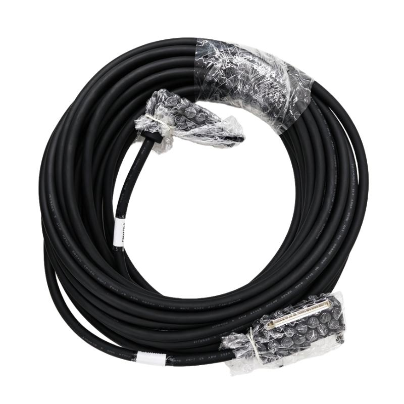
Foxboro P0916FN Terminal Cable installation should focus on connector identification, cable routing, termination integrity, and point-to-point signal verification. In a Foxboro DCS cabinet, a terminal cable is part of the signal path between controller or I/O hardware and field termination points, so a wiring mistake can appear as an I/O module fault even when the electronic hardware is operating normally.
The Foxboro P0916FN should therefore be installed as part of the complete control-system wiring architecture. Before commissioning, technicians need to confirm the cable destination, terminal assignment, connector orientation, shielding arrangement, and continuity of every required signal path.
This Installation Guide presents a practical engineering approach to Foxboro P0916FN setup and commissioning, with emphasis on cabinet wiring, signal verification, and field acceptance testing.
Foxboro P0916FN Terminal Cable Installation Preparation
Before installing the Foxboro P0916FN Terminal Cable, first establish exactly where the cable begins and where it terminates.
The installation drawing should identify:
- Source module
- Destination terminal assembly
- Cable identification
- Signal group
- Pin or terminal assignment
- Shield connection
- Spare conductors, if applicable
Do not rely only on cable appearance. Industrial terminal cables can have similar connectors or physical dimensions while serving completely different signal groups.
A practical preparation checklist is:
| Inspection | Purpose |
|---|---|
| Cable part number | Confirm correct cable |
| Connector type | Prevent incompatible connection |
| Cable ID | Match cabinet documentation |
| Terminal assignment | Avoid channel crossover |
| Shielding | Reduce electrical interference |
| Cable condition | Detect damage before installation |
In one DCS cabinet retrofit, an apparently correct cable was installed because its connector matched the existing hardware. The subsequent point-to-point test showed that two signal positions did not correspond to the updated cabinet drawing. The cable was removed before energization, preventing incorrect field signals from reaching the control system.
Foxboro P0916FN Cable Routing and Cabinet Installation
Mechanical routing is an important part of Foxboro P0916FN Installation.
Terminal cables should be routed so that:
- Connectors are not under mechanical tension.
- Minimum cable-bending requirements are respected.
- Cable trays do not pinch the cable.
- Signal cables are separated from high-power conductors.
- Maintenance personnel can access the termination points.
Avoid forcing the cable into a tight cabinet corner. Excessive bending close to a connector can eventually produce intermittent contact problems.
In mixed-signal cabinets, keep low-level instrumentation and communication wiring away from large motor cables, contactor wiring, and variable-frequency-drive output cables whenever the cabinet design allows.
A clean cable route also improves future Troubleshooting because technicians can trace the signal path without dismantling unrelated wiring.
Foxboro P0916FN Terminal Cable Connector and Termination Setup
The connector is one of the first points to inspect during Foxboro P0916FN Setup.
Before making the final connection, inspect:
- Connector housing
- Contact pins
- Locking mechanism
- Cable strain relief
- Terminal identification
- Signs of oxidation or contamination
The connector should be fully seated and mechanically secured.
A useful field practice is to perform a visual inspection followed by an electrical continuity test before connecting the cable to energized control equipment.
For a multi-conductor cable, test individual conductors against the wiring documentation rather than checking only overall continuity.
A cable can have continuity and still be incorrectly terminated.
For example:
Cable Continuity = PASS
        ↓
Pin-to-Pin Verification
        ↓
Signal Assignment = Correct?
        ↓
Shield / Ground Check
        ↓
Connect to DCS Hardware
This distinction is particularly important during replacement work.
Foxboro P0916FN Terminal Cable Signal Verification
A Foxboro P0916FN Commissioning procedure should include point-to-point verification.
The technician should compare the physical cable with the approved wiring schedule.
A typical verification sequence is:
- Isolate the relevant circuit.
- Identify both cable ends.
- Confirm conductor numbers.
- Check continuity.
- Check for unintended shorts between conductors.
- Verify shield continuity where applicable.
- Confirm terminal assignments.
- Record the test result.
For example, a cable measurement might show:
| Test | Result |
|---|---|
| Conductor continuity | Pass |
| Conductor-to-conductor short | None |
| Shield continuity | Pass |
| Terminal assignment | Verified |
| Connector seating | Verified |
The important point is that electrical testing should be combined with documentation verification.
Foxboro P0916FN Terminal Cable Installation Case Study
During one control-system modification, an engineer installed a replacement terminal cable and performed a point-to-point test before reconnecting the field circuit.
The initial measurement showed correct continuity across all conductors. However, the signal identification did not match the latest I/O schedule.
The team traced the cable back to the cabinet termination and discovered that the documentation and physical termination had been changed during an earlier modification.
Instead of accepting the cable based only on continuity, the engineer compared:
Cable identification → terminal number → I/O channel → field instrument
The discrepancy was corrected before commissioning.
This is a typical example of why cable installation should be treated as an engineering verification task rather than a simple plug-in operation.
Foxboro P0916FN Terminal Cable DCS Commissioning Procedure
Once the physical installation and point-to-point checks are complete, the Foxboro P0916FN can be included in the DCS commissioning process.
Commissioning should verify:
- Correct cable connection
- Correct terminal destination
- Correct I/O channel
- Proper signal response
- Stable operation during normal process conditions
For analog instrumentation, compare the physical signal with the corresponding engineering value.
For discrete signals, verify both states rather than testing only the normal condition.
A practical signal-validation process is:
Field Device
     ↓
Terminal Connection
     ↓
P0916FN Cable
     ↓
I/O Channel
     ↓
DCS Database
     ↓
Operator Display
Testing the complete path is more reliable than checking the cable separately from the control system.
Foxboro P0916FN Cable Commissioning Fault Prevention
Many cable-related problems only appear after equipment is energized.
To reduce commissioning risk, inspect:
- Loose connectors
- Incorrect cable identification
- Pinched conductors
- Improper shield termination
- Incorrect terminal assignments
- Cable damage caused during cabinet installation
During commissioning, change only one variable at a time. If the cable, I/O module, and configuration are all changed simultaneously, determining the source of a subsequent fault becomes much more difficult.
For critical DCS systems, record the final verified cable route and termination information in the maintenance documentation.
Foxboro P0916FN Terminal Cable Installation Best Practices
For long-term reliability, maintenance personnel should periodically inspect accessible cable connections for:
- Mechanical looseness
- Corrosion
- Cable jacket damage
- Excessive bending
- Abnormal heating
- Unapproved modifications
The Foxboro P0916FN Terminal Cable should be considered part of the complete DCS signal circuit. Proper Installation Guide procedures, careful Setup, and documented Commissioning tests can prevent many apparent I/O failures before production begins.