Siemens 6AG1326-2BF10-2AY0 SIPLUS S7-300 SM326 10F-DO Installation Guide, Wiring and Safety Commissioning
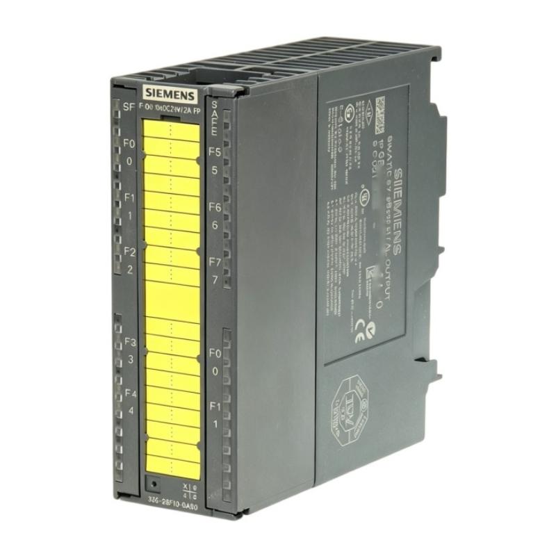
The Siemens 6AG1326-2BF10-2AY0 is a SIPLUS S7-300 SM326 10F-DO fail-safe digital output module with conformal coating and EN 50155 T1 Cat. 1 Class A/B conformity. It is based on the 6ES7326-2BF10-0AB0 and provides 10 fail-safe 24 V DC digital outputs, with a rated output current of 2 A per channel. The module is intended for SIMATIC S7 F safety systems and includes diagnostic functionality.
Siemens 6AG1326-2BF10-2AY0 Digital Output Module Overview
The 6AG1326-2BF10-2AY0 belongs to the SIPLUS S7-300 product family and is designed for applications where fail-safe digital output control and increased environmental robustness are required.
| Parameter | Specification |
|---|---|
| Brand | Siemens |
| Model | 6AG1326-2BF10-2AY0 |
| Product Family | SIPLUS S7-300 |
| Module Type | SM326 10F-DO |
| Output Type | Fail-safe digital output |
| Number of Outputs | 10 |
| Rated Output Voltage | 24 V DC |
| Rated Output Current | 2 A per output |
| Maximum Output Current | 2.4 A under specified conditions |
| Output Technology | Push-pull |
| Short-Circuit Protection | Yes |
| Connection | 1 × 40-pin |
| Power Loss | Approximately 6 W typical |
| Coating | Conformal coating |
| Safety System | SIMATIC S7 F |
The 6AG1326-2BF10-2AY0 is not simply a conventional S7-300 digital output card. Its fail-safe architecture means that the module must be considered as part of the complete safety system.
6AG1326-2BF10-2AY0 Installation Preparation
Before installing the module, verify the complete S7-300/F-system configuration.
The engineer should confirm:
- Correct CPU and F-system architecture
- Correct SM326 module type
- Correct hardware configuration
- Correct module position
- 24 V DC supply availability
- Correct load-voltage distribution
- Compatible field actuators
- Correct 40-pin front connector
- Correct safety-program configuration
- Proper cabinet grounding
- Adequate cabinet cooling
The module should be installed by qualified personnel familiar with Siemens S7 F systems and the machine's safety design.
Because the 6AG1326-2BF10-2AY0 is a safety-related component, commissioning should not be limited to checking whether the output LED changes state.
Siemens 6AG1326-2BF10-2AY0 Mechanical Installation
Before mounting the module, isolate the relevant electrical equipment and follow the machine's lockout and discharge procedures.
Inspect the module carefully for:
- Damaged housing
- Contaminated connectors
- Bent contacts
- Signs of overheating
- Mechanical damage
- PCB contamination
- Loose mounting hardware
The module should be firmly seated in the designated S7-300 installation position.
A poor connection can cause intermittent backplane communication, diagnostic faults, or unexpected module behavior.
6AG1326-2BF10-2AY0 Wiring and 24 V DC Supply
The module uses a 24 V DC supply arrangement and separate load-voltage connections for the output circuits.
When preparing the wiring, identify:
- Module supply
- Load-voltage supply
- Output channel
- 0 V reference
- Connected actuator
- Safety-related interlock
- Protective components
- Field cable
The output load supply should be measured before the actuator is connected.
For example, a commissioning measurement might show:
- Module supply: 24.1 V DC
- Load supply: 24.2 V DC
- 0 V reference: stable
- Output load current: 0.65 A
These measurements provide a useful baseline before enabling the machine.
Siemens 6AG1326-2BF10-2AY0 Output Load Considerations
The module provides 10 digital outputs with a rated output current of 2 A per channel. The specified maximum current can reach 2.4 A under applicable operating conditions.
The connected load must therefore be evaluated carefully.
Typical loads include:
- Solenoid valves
- Contactors
- Relays
- Electromagnetic actuators
- Safety-related control devices
Inductive loads deserve particular attention because switching them can generate voltage transients.
A solenoid valve drawing 0.8 A during normal operation should not automatically be considered a simple 0.8 A load. Its switching frequency, inductive behavior, suppression arrangement, and thermal conditions also affect the output circuit.
6AG1326-2BF10-2AY0 40-Pin Connector Installation
The module uses a 40-pin connection.
Before energization, verify each conductor against the machine electrical drawing.
Pay particular attention to:
- Channel assignment
- Supply polarity
- Load-voltage connections
- Common connections
- Shielding
- Connector seating
- Terminal tightening
- Cross-connected outputs
A wiring error on a safety output should be treated as a safety-system issue, not simply as a conventional I/O wiring mistake.
Siemens 6AG1326-2BF10-2AY0 System Configuration
The hardware configuration must match the installed module.
Check:
- Correct module identification.
- Correct slot position.
- Correct output addresses.
- Correct F-parameters.
- Correct diagnostic settings.
- Correct safety-program assignment.
- Correct actuator assignment.
- Correct fail-safe response.
A mismatch between the physical module and the engineering configuration can produce diagnostic faults even when the wiring is correct.
Conversely, a module being correctly recognized by the CPU does not prove that the safety application has been completely commissioned.
6AG1326-2BF10-2AY0 Setup and Commissioning
Commissioning should start with individual output verification.
For each channel:
Safety command → output state → field voltage → actuator response → machine response
Do not use a simple forced-output test as the only commissioning method for a safety-related system.
The commissioning engineer should verify both normal operation and the defined safe response.
For example:
- Normal command → actuator operates correctly.
- Safety condition → output transitions to the intended safe state.
- Diagnostic condition → system reports the expected fault.
- Fault reset → system returns only when the required reset conditions are satisfied.
Typical 6AG1326-2BF10-2AY0 Commissioning Case
Consider a machine with several 24 V DC safety actuators.
During commissioning, one actuator does not energize even though the engineering configuration appears correct.
A typical field measurement could be:
| Measurement | Result |
|---|---|
| Module supply | 24.1 V DC |
| Load supply | 24.2 V DC |
| Output command | ON |
| Actuator current | 0 A |
| Cable continuity | Normal |
| Module diagnostic | Output-related fault |
The first reaction might be to replace the digital output module.
A better Fault Diagnosis process is to isolate the field load, verify the output group supply, check the actuator circuit, and review the module diagnostic information.
This prevents a field wiring or actuator problem from being incorrectly classified as a module failure.
Siemens 6AG1326-2BF10-2AY0 Installation Verification
Before the machine enters production, record the normal operating condition of every important output.
Recommended commissioning records include:
- Output address
- Connected actuator
- Normal state
- Load voltage
- Load current
- Module diagnostic status
- Safety response
- Reset behavior
These measurements provide a valuable baseline for future Troubleshooting and maintenance.