Allen-Bradley 5094-RTB3I Flex 5000 Isolated Removable Terminal Block Installation Guide (Wiring & Commissioning)
Allen-Bradley 5094-RTB3I isolated removable terminal block installation problems are usually caused by incorrect field wiring, improper isolation requirements, loose terminal connections, or mismatched I/O module configuration rather than terminal block failure. In industrial automation systems, isolated terminal interfaces are often used in applications where signal integrity is critical, and even a small wiring mistake can introduce measurement errors, channel faults, or unexpected machine behavior.
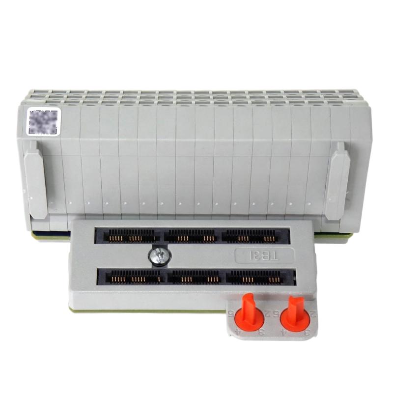
The Allen-Bradley 5094-RTB3I Flex 5000 Isolated Removable Terminal Block is designed for Flex 5000 I/O systems requiring reliable field wiring connection and channel-level isolation. It provides a detachable interface between field devices and I/O modules, helping engineers simplify maintenance while improving signal separation in demanding industrial environments.
Allen-Bradley 5094-RTB3I Isolated Terminal Block Application Overview
The 5094-RTB3I acts as the physical interface between industrial field devices and Flex 5000 I/O modules.
Typical automation structure:
Field Sensors / Actuators||Allen-Bradley 5094-RTB3I Terminal Block||Flex 5000 Isolated I/O Module||ControlLogix / CompactLogix Controller
Typical applications:
- Analog signal measurement systems
- Industrial process monitoring
- Remote I/O cabinets
- Machine automation panels
- Equipment requiring electrical isolation
Main functions:
- Field wiring connection
- Signal isolation support
- Simplified I/O replacement
- Reduced maintenance downtime
- Improved cabinet organization
Isolation is especially important in applications involving:
- Different ground potentials
- Long-distance field wiring
- Sensitive analog signals
- Noisy industrial environments
In one process automation upgrade project, engineers installed a Flex 5000 system with the Allen-Bradley 5094-RTB3I isolated removable terminal block for multiple field instruments.
During commissioning:
- Controller communication: Normal
- I/O module status: Healthy
- Several measurement values: Incorrect
The first assumption was that field transmitters were inaccurate.
The engineering team investigated:
- Terminal wiring
- Signal polarity
- Isolation connection
- Channel configuration
Measured condition:
Before correction:
- PLC communication: Normal
- Sensor output: Stable
- I/O reading: Incorrect fluctuation
Further inspection found that one field signal pair was connected to the wrong terminal position.
After correcting the wiring:
- Analog readings became stable
- Process values matched field instruments
- System commissioning completed successfully
The issue was caused by wiring configuration rather than the 5094-RTB3I terminal block.
Allen-Bradley 5094-RTB3I Installation Preparation and I/O System Planning
Before installing the isolated removable terminal block, engineers should confirm the complete Flex 5000 hardware configuration.
Preparation requirements:
- Verify compatible Flex 5000 module
- Review electrical drawings
- Confirm signal type
- Identify isolated channels
- Prepare shielded field wiring
Installation checklist:
| Inspection Item | Engineering Requirement |
|---|---|
| Terminal block type | Match Flex 5000 I/O module |
| Signal wiring | Correct channel assignment |
| Isolation requirement | Match application needs |
| Cable selection | Industrial shielded cable |
| Grounding | Correct shield and earth connection |
A common field mistake is treating an isolated terminal block as a standard terminal interface.
Isolation functions depend on:
- Correct wiring method
- Proper module selection
- Correct field grounding
Incorrect installation may cause:
- Signal interference
- Measurement deviation
- Unexpected I/O alarms
Allen-Bradley 5094-RTB3I Wiring Installation and Isolation Verification
Proper wiring is essential for maintaining signal quality.
Field Signal Connection Inspection
Engineers should verify:
- Terminal numbering
- Positive and negative signal connection
- Shield termination
- Wire tightening
Poor wiring practices may result in:
- Intermittent signals
- Incorrect measurement values
- Channel instability
Isolation Circuit Inspection
Check:
- Channel separation requirements
- Field ground conditions
- External device reference points
During one field installation:
Initial condition:
- Temperature transmitters connected
- PLC values fluctuated
- Network communication normal
Engineering measurements:
- Field transmitter output: Stable
- Terminal connection: Correct
- PLC reading: Unstable
Further inspection found:
- Signal cable shield was grounded at multiple points
After correcting shielding:
- Electrical noise decreased
- Temperature values stabilized
- Process monitoring returned to normal
Allen-Bradley 5094-RTB3I Setup and System Configuration
The configuration stage ensures the physical wiring matches the control application.
Important checks:
- Module identification
- Channel assignment
- Signal range
- Input/output parameters
Typical commissioning logic:
IF Terminal_Block = CorrectAND Channel_Config = MatchingAND Signal_Type = ValidTHENAccept_Field_Data
Engineers should compare:
- PLC tag configuration
- Hardware channel numbers
- Electrical drawings
This prevents common commissioning errors where software configuration does not match actual field wiring.
Allen-Bradley 5094-RTB3I Commissioning Validation and Performance Testing
Final commissioning should verify signal quality and system response.
Signal Verification
Check:
- Field signal value
- PLC displayed value
- Signal stability
Isolation Performance Test
Verify:
- No unwanted ground loops
- Stable readings
- Correct channel separation
Example commissioning results:
Before correction:
- Process values fluctuated
- Operator adjustments were required
After correction:
- Stable signal transmission
- Accurate PLC monitoring
- Reliable machine operation
A successful Allen-Bradley 5094-RTB3I installation requires correct terminal selection, accurate wiring, and proper isolation verification.