Siemens 6AG1326-2BF10-2AY0 Troubleshooting Guide: Digital Output Fault Diagnosis
The Siemens 6AG1326-2BF10-2AY0 Troubleshooting Guide should separate logic faults, power-supply faults, field wiring faults, actuator faults, diagnostic conditions, and actual module failures.
The correct troubleshooting sequence is generally:
Safety logic → module status → supply → output group → field wiring → actuator → module hardware
This approach is more reliable than immediately replacing the SM326 module.
6AG1326-2BF10-2AY0 Output Does Not Turn On
If an expected output remains OFF, first determine whether the safety program actually commands the output ON.
Check:
- F-program logic
- Enable conditions
- Interlocks
- Module status
- Output address
- Load-voltage supply
- Diagnostic status
If the safety program intentionally keeps the output OFF, the hardware may be completely healthy.
If the program commands ON but the physical output remains inactive, continue toward the power and field circuits.
Siemens 6AG1326-2BF10-2AY0 Short-Circuit Troubleshooting
The digital outputs have short-circuit protection.
When a channel reports a short-circuit condition, do not repeatedly reset the module without investigating the field circuit.
Check:
- Output conductor insulation
- Actuator coil
- Connector condition
- Cable-to-ground faults
- Incorrect wiring
- Damaged field device
For example, if a solenoid normally draws approximately 0.7 A but suddenly draws several times its normal current, inspect the solenoid and field wiring before assuming that the SM326 output stage has failed.
The protection function may be correctly preventing damage to the output.
6AG1326-2BF10-2AY0 Output Overload Diagnosis
An overload does not necessarily mean that there is a direct short circuit.
Consider a valve output with this operating history:
| Condition | Normal | Fault |
|---|---|---|
| Output current | 0.8 A | 1.7 A |
| Load voltage | 24.2 V | 24.1 V |
| Command | ON | ON |
| Actuator temperature | Normal | High |
The increased current suggests that the actuator itself may have deteriorated.
Possible causes include:
- Aging coil
- Mechanical actuator failure
- Incorrect supply voltage
- Damaged cable
- Partial insulation failure
- Excessive switching frequency
Replacing the output module without checking the actuator can result in repeated failures.
Siemens 6AG1326-2BF10-2AY0 Diagnostic Alarm Troubleshooting
When a diagnostic alarm occurs, record the condition before resetting the system.
Useful information includes:
- Affected channel
- Output command
- Physical output state
- Load voltage
- Module status
- Diagnostic information
- Machine operating condition
- Time of occurrence
A reset that temporarily clears the diagnostic indication does not necessarily mean that the underlying fault has disappeared.
If the same channel repeatedly faults under the same operating condition, the failure pattern becomes an important part of the diagnosis.
6AG1326-2BF10-2AY0 Output Group Fault Diagnosis
The output channels are arranged into groups, making group-level comparison useful during troubleshooting.
If only one channel fails, investigate the individual actuator and wiring first.
If several outputs in the same group fail simultaneously, check:
- Common load supply
- Group wiring
- Common protection
- Thermal loading
- Connector condition
If all outputs become unavailable simultaneously, investigate system-level conditions such as module supply, backplane communication, F-system status, and configuration.
Siemens 6AG1326-2BF10-2AY0 Intermittent Fault Troubleshooting
An intermittent output fault can be difficult to reproduce because the module may operate normally during inspection.
Record the following:
- Operating time before failure
- Cabinet temperature
- Output current
- Load voltage
- Output state
- Diagnostic status
- Machine operating mode
For example:
| Parameter | Normal | During Fault |
|---|---|---|
| Load voltage | 24.2 V | 24.1 V |
| Output current | 0.75 A | 0.76 A |
| Cabinet temperature | 30°C | 47°C |
| Output state | ON | OFF |
| Field wiring | Normal | Normal |
If the supply and current remain stable while the output disappears after the cabinet heats up, thermal conditions, connectors, and the module itself should be investigated.
6AG1326-2BF10-2AY0 Thermal Fault Diagnosis
The module has a typical power loss of approximately 6 W.
Thermal performance is affected by:
- Number of energized outputs
- Current per output
- Total group current
- Cabinet temperature
- Installation orientation
- Ventilation
- Load type
A module operating ten low-current loads has a different thermal condition from one operating several high-current actuators simultaneously.
If output faults begin only after prolonged operation, compare the module temperature and output loading with the normal commissioning baseline.
Siemens 6AG1326-2BF10-2AY0 Fault Diagnosis: One Channel or Multiple Channels
The number of affected outputs is an important diagnostic clue.
One output fails
Focus on:
- Field actuator
- Output cable
- Connector
- Channel configuration
- Individual output stage
Several outputs in one group fail
Focus on:
- Common supply
- Group wiring
- Group loading
- Thermal conditions
All outputs fail
Focus on:
- Module supply
- Backplane connection
- F-system status
- Hardware configuration
- Common safety conditions
This approach can prevent unnecessary replacement of an otherwise healthy module.
Repair or Replacement of the 6AG1326-2BF10-2AY0
Because the 6AG1326-2BF10-2AY0 is a fail-safe digital output module, internal repair should not be treated like repairing a conventional relay or standard digital output card.
If the external power supply, field wiring, actuators, configuration, and safety logic have all been verified and the same hardware fault remains repeatable, replacing the module with the correct compatible unit is generally the more controlled maintenance approach.
After replacement, the complete safety function should be recommissioned.
Do not bypass a safety output merely to restore production.
Siemens 6AG1326-2BF10-2AY0 Technical FAQ
What is Siemens 6AG1326-2BF10-2AY0?
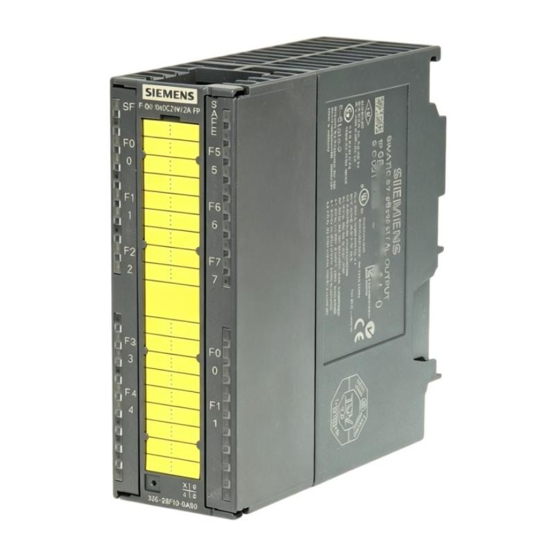
It is a SIPLUS S7-300 SM326 10F-DO fail-safe digital output module with conformal coating and EN 50155 T1 Cat. 1 Class A/B conformity.
How many outputs does the 6AG1326-2BF10-2AY0 have?
It provides 10 fail-safe digital outputs.
What is the output voltage?
The rated digital output voltage is 24 V DC.
What is the rated output current?
The rated output current is 2 A per output, with a specified maximum of 2.4 A under applicable conditions.
Is the 6AG1326-2BF10-2AY0 a standard S7-300 digital output module?
No. It is an SM326 10F-DO fail-safe digital output module intended for SIMATIC S7 F systems.
Does it provide short-circuit protection?
Yes. The digital outputs have short-circuit protection.
What connector does the module use?
The module uses a 40-pin connection.
Why does one output fail while the others continue working?
The fault may be limited to the connected actuator, field cable, output channel, or channel-specific configuration. Compare the affected channel with a healthy channel before replacing the module.
Why do several outputs fail simultaneously?
A simultaneous failure can indicate a common load supply, group wiring problem, module supply issue, backplane problem, or safety-system condition.
What should be checked before replacing the module?
Check the safety logic, module diagnostics, 24 V DC supply, output group supply, field wiring, actuator, and system configuration first. Only after these areas are verified should the module itself be considered the primary fault source.