Siemens 6AG1193-4CL30-7AA0 SIPLUS ET 200S TM-E15C24-AT Terminal Module Installation Guide, Wiring and Commissioning
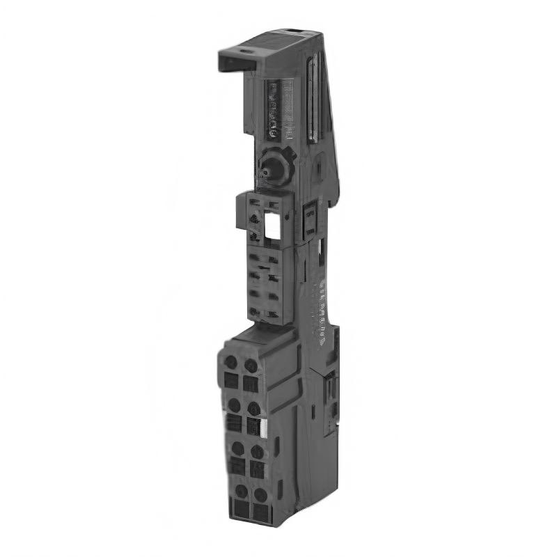
The Siemens 6AG1193-4CL30-7AA0 is a SIPLUS ET 200S TM-E15C24-AT terminal module with conformal coating, designed for the 2 AI TC High Feature electronic module. It has a 15 mm width, spring-loaded terminals, access to the AUX1 bus, and a 0 to +70°C operating temperature range. The module is based on the 6ES7193-4CL30-0AA0 terminal module design.
Siemens 6AG1193-4CL30-7AA0 Terminal Module Overview
The 6AG1193-4CL30-7AA0 is part of the SIPLUS ET 200S distributed I/O platform. Unlike an electronic input or output module, the terminal module provides the physical connection and electrical interface between the field wiring and the associated ET 200S electronic module.
Its main characteristics are:
| Parameter | Specification |
|---|---|
| Brand | Siemens |
| Model | 6AG1193-4CL30-7AA0 |
| Product Family | SIPLUS ET 200S |
| Module Type | TM-E15C24-AT Terminal Module |
| Compatible Electronic Module | 2 AI TC High Feature |
| Width | 15 mm |
| Height | 132 mm |
| Depth | 43 mm |
| Terminal Type | Spring-loaded |
| AUX1 | Terminal access |
| AUX1 | Continuous through module |
| Conformal Coating | Yes |
| Operating Temperature | 0 to +70°C |
| Approx. Weight | 55–70 g |
The terminal module is therefore an important part of the overall System Configuration, even though it does not perform the actual temperature measurement itself.
6AG1193-4CL30-7AA0 Installation Preparation
Before installing the terminal module, verify that the correct electronic module is being used.
The 6AG1193-4CL30-7AA0 is specifically associated with the 2 AI TC High Feature electronic module. It should not be treated as a universal ET 200S terminal base.
Before installation, check:
- ET 200S station configuration
- Correct terminal module
- Compatible electronic module
- Field thermocouple type
- Channel assignment
- AUX1 requirements
- Terminal wiring
- Cabinet temperature
- Mechanical clearance
- Module coding
A common installation mistake is selecting a terminal module based only on physical appearance. ET 200S terminal modules can have similar dimensions while having different electrical functions and connection arrangements.
Siemens 6AG1193-4CL30-7AA0 Mechanical Installation
The terminal module has a compact 15 × 132 × 43 mm form factor, allowing it to be installed in the narrow ET 200S station structure.
Before installation:
- Isolate the relevant control cabinet equipment.
- Inspect the terminal module.
- Check the mounting area.
- Confirm the correct module position.
- Install the terminal module securely.
- Verify that the adjacent ET 200S modules are correctly aligned.
Pay particular attention to the mechanical connection between the terminal module and the electronic module.
A partially seated electronic module can produce intermittent measurement faults that may initially appear to be caused by the temperature sensor.
6AG1193-4CL30-7AA0 Wiring and Spring Terminals
The 6AG1193-4CL30-7AA0 uses spring-loaded terminals. This provides a practical advantage for field wiring because conductors can be connected without relying on conventional screw-terminal tightening torque.
During wiring, check:
- Correct thermocouple channel
- Correct polarity
- Correct conductor type
- Proper conductor insertion
- Secure spring-terminal connection
- Cable routing
- Shielding
- AUX1 wiring where required
Thermocouple wiring deserves special attention because incorrect polarity or inappropriate extension cable can produce temperature readings that appear plausible but are actually incorrect.
Siemens 6AG1193-4CL30-7AA0 Thermocouple Wiring
Because the terminal module is intended for the 2 AI TC High Feature electronic module, the associated field wiring should be designed around thermocouple measurement.
The engineer should verify the complete signal path:
Thermocouple → field cable → terminal module → electronic module → ET 200S station → PLC
If the temperature reading is incorrect, do not automatically replace the terminal module.
Check the signal path from the sensor toward the PLC.
Typical causes include:
- Reversed thermocouple polarity
- Wrong thermocouple type
- Incorrect extension cable
- Loose terminal
- Damaged sensor
- Electrical interference
- Incorrect channel configuration
6AG1193-4CL30-7AA0 AUX1 Connection
The 6AG1193-4CL30-7AA0 provides access to AUX1, with AUX1 continuously connected through the terminal module.
When AUX1 is used, confirm the intended electrical function before connecting external circuits.
Do not assume AUX1 is equivalent to a general-purpose 24 V DC terminal simply because it is physically accessible.
The actual electrical use should follow the ET 200S station design and the corresponding module documentation.
Siemens 6AG1193-4CL30-7AA0 System Configuration
The terminal module itself does not replace the electronic temperature-input module.
The correct configuration should therefore include:
- ET 200S interface module
- 6AG1193-4CL30-7AA0 terminal module
- Compatible 2 AI TC High Feature module
- Correct channel configuration
- Correct thermocouple type
- Correct temperature range
- Correct diagnostics
The PLC should be configured according to the actual electronic module rather than the terminal module alone.
This distinction is important during Setup and Commissioning.
6AG1193-4CL30-7AA0 Commissioning Procedure
After installation, perform the commissioning in stages.
First verify the mechanical installation and wiring.
Then check the temperature input with a known process condition.
For example, if a temperature sensor is measuring an ambient condition of approximately 25°C, the PLC reading should be reasonably consistent with the expected value after considering sensor accuracy and installation conditions.
A commissioning record could contain:
| Test Item | Example Result |
|---|---|
| Terminal module installed | Correct |
| Electronic module recognized | Yes |
| Sensor channel | Channel 1 |
| Ambient temperature | 24.8°C |
| PLC temperature value | 25.1°C |
| Diagnostic status | Normal |
| AUX1 connection | Verified |
The exact expected measurement depends on the thermocouple type, process conditions, and configured measurement parameters.
Typical 6AG1193-4CL30-7AA0 Commissioning Case
A typical field commissioning situation involves a temperature channel showing approximately -10°C while the process is actually around 30°C.
The engineer first checks the PLC configuration and confirms that the input channel is configured for the intended thermocouple.
The next measurement finds that the thermocouple wiring has been reversed.
After correcting the polarity, the measured value changes to approximately 29–31°C.
This is a useful example of practical Fault Diagnosis: when a temperature value is clearly abnormal but the electronic module reports no hardware fault, inspect sensor type, polarity, extension cable, and terminal wiring before replacing the ET 200S hardware.
Siemens 6AG1193-4CL30-7AA0 Installation Verification
Before the machine is released, verify:
- Terminal module identification
- Electronic module compatibility
- Mechanical seating
- Spring-terminal connections
- Thermocouple polarity
- Sensor type
- Channel assignment
- AUX1 wiring
- PLC temperature value
- Diagnostic status
Record normal readings so that future Troubleshooting can be based on an established baseline.