Siemens 6AG1193-4CL30-7AA0 Troubleshooting Guide: Terminal Module Fault Diagnosis and Repair
The Siemens 6AG1193-4CL30-7AA0 Troubleshooting Guide should begin with the signal path rather than assuming the terminal module itself is defective.
For temperature-measurement applications, the most useful diagnostic sequence is:
Sensor → cable → terminal connection → terminal module → electronic module → ET 200S station → PLC configuration
This prevents sensor and wiring problems from being incorrectly diagnosed as terminal-module failures.
6AG1193-4CL30-7AA0 Temperature Reading Is Incorrect
If the temperature value is wrong, compare the PLC value with an independent measurement.
For example:
- Independent reference: 80°C
- PLC reading: 42°C
First verify the sensor and thermocouple type.
Then inspect:
- Sensor wiring
- Polarity
- Extension cable
- Terminal connection
- Electronic module configuration
- Channel assignment
If the terminal connections are secure and another channel operates correctly with the same configuration, the comparison can help isolate the fault.
Siemens 6AG1193-4CL30-7AA0 Intermittent Temperature Signal
An intermittent temperature signal is often associated with a loose field connection or damaged sensor cable.
A typical pattern could be:
| Condition | Normal | Fault |
|---|---|---|
| Temperature | 65°C | 65 → 42 → 68°C |
| Process condition | Stable | Stable |
| Cable movement | None | Occasional |
| Terminal connection | Normal | Suspect |
If the process itself is stable but the PLC value suddenly jumps, inspect the physical signal path.
Spring-loaded terminals reduce the need for periodic screw-terminal retightening, but they do not eliminate problems caused by incorrectly prepared conductors, damaged cables, poor insertion, or mechanical stress.
6AG1193-4CL30-7AA0 Open-Circuit Troubleshooting
A thermocouple circuit can produce abnormal or diagnostic readings when the sensor circuit is open.
Check:
- Sensor continuity
- Extension cable
- Terminal insertion
- Connector condition
- Thermocouple junction
- Field wiring
If the sensor cable is broken near the machine's moving section, the fault may appear only when the equipment moves.
In such cases, static continuity testing may not reproduce the fault.
A flex test of the cable, performed safely and without exposing personnel to hazardous machinery, can help identify an intermittent conductor.
Siemens 6AG1193-4CL30-7AA0 Wrong Thermocouple Type
Another common troubleshooting issue is a mismatch between the physical sensor and the configured input type.
For example, if the actual sensor is one thermocouple type but the electronic module is configured for another, the PLC can display a temperature value that looks reasonable while still being incorrect.
Therefore, verify:
- Sensor type
- Extension cable type
- Channel configuration
- Temperature range
- Polarity
Do not rely only on the color of the cable insulation because color conventions can differ between manufacturers and regions.
6AG1193-4CL30-7AA0 Terminal Connection Fault Diagnosis
If one temperature channel is unstable while another channel on the same station remains stable, compare the two physical connections.
Check:
- Conductor insertion depth
- Spring-terminal condition
- Cable preparation
- Mechanical strain
- Terminal assignment
- Sensor cable routing
For example, if Channel 1 remains at 72°C while Channel 2 fluctuates between 70°C and 95°C under a stable process condition, the fault is more likely to be channel-specific than a complete station communication failure.
Siemens 6AG1193-4CL30-7AA0 Troubleshooting With AUX1
If an AUX1-connected circuit causes unexpected behavior, isolate the auxiliary circuit from the temperature measurement system where the machine design permits.
Then verify:
- AUX1 wiring
- Common reference
- External load
- Electrical compatibility
- Unintended connections
Do not assume that an auxiliary connection has no influence on the rest of the station simply because the temperature channels themselves appear correctly wired.
6AG1193-4CL30-7AA0 Intermittent Module Recognition
If the electronic module is intermittently recognized by the ET 200S station, inspect the physical module connection.
Possible causes include:
- Poor mechanical seating
- Contaminated contacts
- Damaged connector interface
- Mechanical vibration
- Cabinet temperature
- Station configuration problems
A useful comparison is to record whether the problem affects only one electronic module or multiple modules.
If several modules disappear simultaneously, investigate the station-level interface or power supply before replacing the terminal module.
Siemens 6AG1193-4CL30-7AA0 Thermal Troubleshooting
The 6AG1193-4CL30-7AA0 has a specified operating range of 0 to +70°C and uses conformal coating for enhanced environmental protection.
If the station operates near the upper temperature range, inspect:
- Cabinet ventilation
- Local heat sources
- Module spacing
- Airflow
- Cabinet temperature
- Connection stability
For example, if a temperature input works normally at 30°C cabinet temperature but becomes unstable when the cabinet reaches 65°C, thermal conditions should be considered as part of the Fault Diagnosis.
6AG1193-4CL30-7AA0 Fault Diagnosis: Terminal Module or Electronic Module?
This distinction is important.
The terminal module provides the physical field connection, while the associated electronic module performs the actual temperature-input processing.
If the field wiring is correct but the measured temperature remains incorrect, the electronic module and its configuration should also be investigated.
A practical isolation sequence is:
Known-good sensor → known-good cable → terminal connection → electronic module → PLC value
This method can identify whether the fault is in the field connection or in the electronic measurement system.
Siemens 6AG1193-4CL30-7AA0 Replacement and Repair
If the terminal module has a damaged housing, defective connection mechanism, damaged contacts, or other physical failure, replacement is normally more appropriate than attempting component-level repair.
Before replacing it:
- Record the existing station configuration.
- Label all field conductors.
- Photograph the wiring if permitted by the maintenance procedure.
- Isolate the equipment.
- Replace the terminal module with the correct compatible version.
- Reconnect the field wiring.
- Verify the electronic module.
- Perform temperature-input testing.
After replacement, compare the measured values with the previously recorded baseline.
Siemens 6AG1193-4CL30-7AA0 Technical FAQ
What is Siemens 6AG1193-4CL30-7AA0?
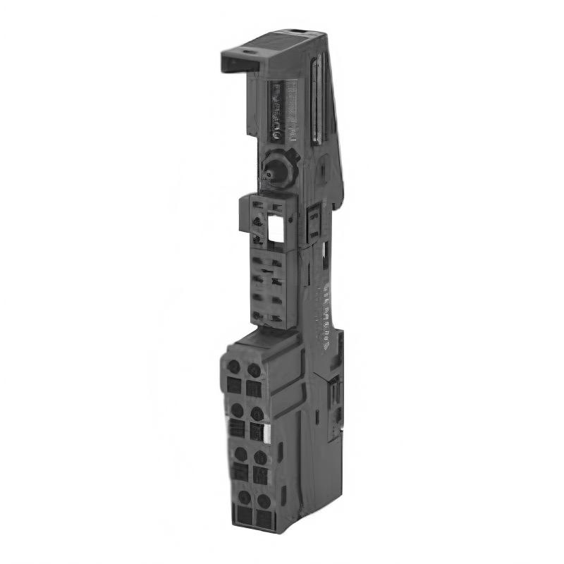
It is a SIPLUS ET 200S TM-E15C24-AT terminal module designed for the 2 AI TC High Feature electronic module.
Is 6AG1193-4CL30-7AA0 an analog input module?
No. It is a terminal module. The associated electronic module performs the actual thermocouple measurement.
What electronic module is it designed for?
It is designed for the 2 AI TC High Feature electronic module.
What is the width of the 6AG1193-4CL30-7AA0?
The terminal module has a 15 mm width.
What are its dimensions?
The commonly specified dimensions are approximately 15 × 132 × 43 mm.
What type of terminals does it use?
It uses spring-loaded terminals.
Does the terminal module provide AUX1 access?
Yes. The 6AG1193-4CL30-7AA0 provides terminal access to AUX1, with AUX1 continuously interconnected through the module.
What is its operating temperature range?
The specified operating temperature range is 0 to +70°C.
Why is the temperature reading incorrect even though the terminal module appears normal?
The problem may be caused by the thermocouple, polarity, extension cable, electronic module configuration, field wiring, or PLC configuration rather than the terminal module itself.
What should be checked first when troubleshooting?
Start with the sensor, thermocouple type, polarity, cable, spring-terminal connection, electronic module, and PLC configuration before replacing the 6AG1193-4CL30-7AA0.