Siemens 6AG1343-1EX30-7XE0 Communication Processor Installation Guide: Ethernet Setup and Commissioning
Siemens 6AG1343-1EX30-7XE0 communication processor installation requires correct Ethernet configuration, network addressing, PLC communication settings, and hardware commissioning. In industrial automation systems, most communication failures are not caused by the Communication Processor itself but by incorrect IP configuration, network topology, firmware compatibility, or cable problems.
Siemens 6AG1343-1EX30-7XE0 Communication Processor Application
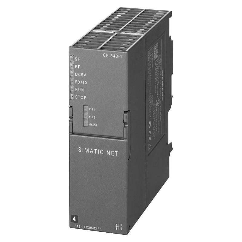
The Siemens 6AG1343-1EX30-7XE0 is a SIPLUS NET CP 343-1 communication processor designed for SIMATIC S7-300 systems. It provides Industrial Ethernet communication through ISO and TCP/IP protocols and supports PROFINET IO Controller or PROFINET IO Device functions. The module also includes an integrated 2-port Ethernet switch for industrial network applications.
Typical applications include:
- PLC-to-SCADA communication
- Industrial Ethernet networking
- PROFINET field device connection
- Remote diagnostics
- Machine communication systems
- Production-line data exchange
- Industrial automation network expansion
Unlike a standard I/O Module, the CP 343-1 does not process analog or digital signals directly. Its main role is to provide a reliable communication bridge between the SIMATIC S7-300 PLC and industrial Ethernet devices.
Siemens 6AG1343-1EX30-7XE0 Technical Installation Specifications
Before installation, verify the communication processor specifications.
| Parameter | Specification |
|---|---|
| Manufacturer | Siemens |
| Model | 6AG1343-1EX30-7XE0 |
| Product Type | Communication Processor |
| Product Family | SIPLUS NET CP 343-1 |
| Communication Interface | Industrial Ethernet |
| Supported Protocols | ISO / TCP/IP / PROFINET |
| Ethernet Ports | 2 × RJ45 |
| Transmission Rate | 10/100 Mbit/s |
| Supply Voltage | 24 V DC |
| Dimensions | 40 × 125 × 120 mm |
| Weight | 0.287 kg / 0.63 lb |
| Operating Temperature | -25 °C to +70 °C |
The module is based on the CP 343-1 platform and includes conformal coating for enhanced resistance in demanding industrial environments.
Siemens 6AG1343-1EX30-7XE0 Installation Preparation
Before installing the communication processor, confirm the following:
- S7-300 rack compatibility
- CPU communication capability
- Power supply stability
- Ethernet network design
- Correct mounting position
- Proper grounding
- Network cable quality
Inspect the module before installation:
- Check housing condition
- Check Ethernet connectors
- Check front connector
- Verify no mechanical damage exists
- Confirm storage conditions
A communication module failure is often difficult to diagnose because network problems can appear identical to hardware problems.
A systematic installation approach should separate:
Hardware → Network → Configuration → Application Communication
Siemens 6AG1343-1EX30-7XE0 Ethernet Wiring and Network Setup
The Ethernet wiring quality directly affects communication reliability.
During installation, check:
- RJ45 connector condition
- Industrial Ethernet cable type
- Cable shielding
- Network topology
- Switch configuration
- Grounding method
- Cable routing
Avoid installing Ethernet cables together with:
- Motor power cables
- Frequency converter cables
- High-current conductors
- Strong electromagnetic interference sources
A communication processor may appear defective when the actual problem is packet loss caused by poor network installation.
Siemens 6AG1343-1EX30-7XE0 IP Address Configuration
The first Setup task is assigning the correct network parameters.
The engineer should verify:
- IP address
- Subnet mask
- Network gateway
- Device name
- PROFINET configuration
- Communication partner settings
A typical commissioning logic is:
Hardware Installation → Network Parameter Setup → Download Configuration → Communication Test → Application Validation
If multiple devices use incorrect or duplicated IP addresses, communication instability may appear randomly and become difficult to reproduce.
Siemens 6AG1343-1EX30-7XE0 PROFINET Commissioning
During Commissioning, verify the communication path step by step.
A practical validation sequence:
- Confirm module recognition by the S7-300 CPU.
- Check Ethernet link status.
- Verify IP communication.
- Test PROFINET device connection.
- Monitor diagnostic information.
- Confirm application data exchange.
The communication test should not stop at “network connected”.
A device can have an active Ethernet link while still having incorrect PLC communication parameters.
Siemens 6AG1343-1EX30-7XE0 System Configuration
Correct System Configuration is essential for stable communication.
Check:
- Correct hardware configuration in engineering software.
- Correct CP 343-1 selection.
- Correct firmware compatibility.
- Correct IP parameters.
- Correct communication blocks.
- Correct PROFINET configuration.
- Correct partner device settings.
For industrial applications, the communication architecture should be documented clearly.
A small configuration difference between the PLC project and the actual field network can prevent communication even when all hardware appears normal.
Siemens 6AG1343-1EX30-7XE0 Field Commissioning Case
In one industrial commissioning case, a machine PLC could detect the communication processor, but the SCADA system repeatedly lost connection.
The initial assumption was that the CP 343-1 hardware was unstable.
The engineer checked the communication chain:
PLC CPU → CP 343-1 → Ethernet Switch → SCADA Server
The Ethernet link remained active, but network diagnostics showed repeated communication interruptions.
Further investigation found that another device on the same network had been assigned the same IP address.
After correcting the network configuration, communication became stable without replacing the Siemens communication processor.
This case demonstrates why Communication Processor Fault Diagnosis must include the entire network environment.
Siemens 6AG1343-1EX30-7XE0 Installation Troubleshooting
| Observation | Initial Diagnostic Direction |
|---|---|
| Module not recognized | Rack installation and power supply |
| Ethernet link inactive | Cable, connector and switch |
| PLC communication unavailable | IP configuration and protocol settings |
| Intermittent connection | Network interference or duplicate address |
| PROFINET device missing | Device name and hardware configuration |
| Communication delay | Network load and topology |
A reliable Installation Guide should always include network-level verification instead of focusing only on the communication module.