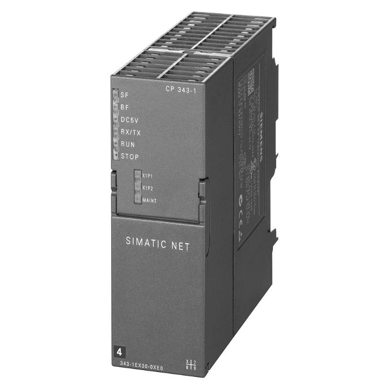
Siemens 6AG1343-1EX30-7XE0 Communication Processor Troubleshooting Guide: Fault Diagnosis and Repair
Siemens 6AG1343-1EX30-7XE0 troubleshooting should begin with communication behavior analysis rather than immediate module replacement. Ethernet communication faults are often caused by network configuration, IP conflicts, cable problems, or incorrect PLC settings.
Siemens 6AG1343-1EX30-7XE0 Communication Fault Symptoms
Common communication problems include:
- PLC cannot communicate with SCADA
- PROFINET devices disappear
- Ethernet connection repeatedly drops
- Communication timeout alarms appear
- Data exchange becomes unstable
- Diagnostic LEDs show abnormal status
- Remote access becomes unavailable
The first diagnostic question should be:
Is the communication processor unavailable, or is the network connection failing somewhere else?
This distinction determines the troubleshooting direction.
Siemens 6AG1343-1EX30-7XE0 Fault Diagnosis Process
A practical Fault Diagnosis sequence is:
CPU → Communication Processor → Ethernet Cable → Switch → Network Device → Application
Start by checking whether the S7-300 CPU recognizes the CP 343-1.
Then verify:
- Module diagnostic information
- Ethernet link status
- Network addressing
- Communication partner availability
- Application-layer communication
A communication failure should be traced through the complete data path.
Replacing the Communication Processor before checking the network often increases downtime without solving the actual problem.
Siemens 6AG1343-1EX30-7XE0 Troubleshooting: Network Communication Loss
A common field failure pattern is intermittent communication loss.
The machine may operate normally, then suddenly lose connection with the upper-level system.
The engineer should collect evidence:
- Time of communication failure
- Network device status
- Diagnostic buffer information
- Ethernet error counters
- Cable condition
- Switch events
If the communication failure occurs randomly, investigate:
- Duplicate IP addresses
- Network congestion
- Poor cable shielding
- Industrial switch problems
- Electrical interference
Intermittent faults require trend analysis rather than a single hardware check.
Siemens 6AG1343-1EX30-7XE0 Communication Processor Case Study
A representative maintenance case involved a production machine where the operator reported frequent SCADA disconnections.
The CP 343-1 module appeared normal, and the Ethernet LEDs remained active.
The engineer compared:
PLC communication status → Network switch → SCADA connection
The PLC diagnostics showed no hardware fault.
Further network analysis found that the switch port occasionally lost link due to a damaged Ethernet connector.
After replacing the network cable, communication returned to stable operation.
The Communication Processor was functioning correctly throughout the event.
Siemens 6AG1343-1EX30-7XE0 IP Address Fault Diagnosis
Incorrect IP configuration is one of the most common causes of industrial Ethernet problems.
Typical symptoms:
- Device cannot be reached
- Communication works temporarily
- Multiple devices disconnect
- Network diagnostics show unstable behavior
Check:
- Duplicate IP addresses
- Incorrect subnet mask
- Incorrect gateway
- Wrong device name
- Incorrect PROFINET configuration
A network scan can help identify whether another device is using the same address.
Changing hardware before correcting addressing problems usually does not solve the fault.
Siemens 6AG1343-1EX30-7XE0 PROFINET Troubleshooting
PROFINET communication problems require checking both hardware and software configuration.
Investigate:
- Device name assignment
- IO device configuration
- Communication relationship
- Hardware configuration download
- Network topology
- Diagnostic messages
If a PROFINET device is missing after startup, confirm that the engineering project matches the actual field installation.
A replaced field device may require a new device-name assignment before communication can resume.
Siemens 6AG1343-1EX30-7XE0 Hardware Fault Diagnosis
Although many communication problems are network-related, hardware failure can occur.
Possible hardware symptoms:
- No Ethernet link
- Module diagnostic fault
- Abnormal LED indication
- Communication failure with a known-good network
- Failure after power cycling
Before replacing the module, confirm:
- Stable 24 V DC supply
- Correct rack connection
- Known-good Ethernet cable
- Correct network parameters
- Functional communication partner
A hardware replacement decision should be based on eliminated external causes.
Siemens 6AG1343-1EX30-7XE0 Repair and Replacement Decision
Replace the communication processor only after confirming:
- Network cables are healthy
- Ethernet switch operates correctly
- IP configuration is correct
- PLC hardware configuration is correct
- Communication partner is available
- Power supply is stable
If the CP 343-1 fails communication tests with a verified network environment, replacement becomes a reasonable repair action.
Siemens 6AG1343-1EX30-7XE0 Post-Repair Validation
After replacement, perform complete communication validation.
Check:
- Module recognition
- IP configuration
- Ethernet link
- PROFINET communication
- SCADA connection
- Data exchange stability
- Diagnostic status
Operate the machine under normal production conditions and monitor communication stability over time.
A successful repair should restore reliable communication, not just temporary connection.
Siemens 6AG1343-1EX30-7XE0 Troubleshooting Checklist
| Fault Condition | Diagnostic Priority |
|---|---|
| No communication | IP settings and network connection |
| Intermittent communication | Cable, switch and interference |
| PROFINET failure | Device name and configuration |
| Module unavailable | Power and rack connection |
| SCADA disconnects | Network path analysis |
| Fault returns after replacement | External network cause |