Siemens 6AG1511-1AK02-2AB0 Central Processing Unit Installation Guide (PLC Setup & Commissioning)
Siemens 6AG1511-1AK02-2AB0 PLC CPU Installation Guide for S7-1500 Automation Systems
Siemens 6AG1511-1AK02-2AB0 Central Processing Unit installation depends on correct mounting, power wiring, hardware configuration, and communication setup. In practice, a PLC CPU that powers up but does not enter the expected operating state is often affected by configuration or module integration rather than a defective processor.
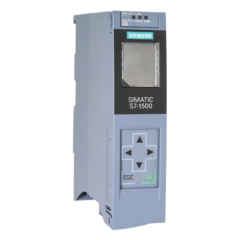
The Siemens 6AG1511-1AK02-2AB0 is an S7-1500-family Central Processing Unit intended for industrial automation applications. During installation, the CPU should be treated as the control center of the complete PLC system. The commissioning engineer therefore needs to verify not only the CPU itself, but also the associated I/O modules, communication interfaces, engineering project, and field wiring.
A reliable Siemens 6AG1511-1AK02-2AB0 Installation Guide should follow the actual engineering sequence: prepare the cabinet, install the CPU, establish power and communication connections, configure the PLC project, transfer the program, and then validate the system under operating conditions.
Siemens 6AG1511-1AK02-2AB0 PLC CPU Installation Preparation
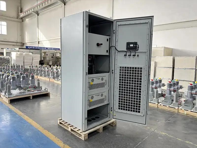
Before mounting the Siemens 6AG1511-1AK02-2AB0 PLC CPU, inspect the complete control cabinet rather than starting with software configuration.
The preparation stage should cover:
- CPU mounting position
- Available expansion modules
- Power supply arrangement
- PROFINET network topology
- Ethernet cable routing
- Cabinet grounding
- Ventilation and heat dissipation
- Engineering workstation connection
The CPU should be installed where maintenance personnel can access status indicators and network connections without removing unrelated equipment.
A practical cabinet inspection also looks for sources of electrical interference. Variable-frequency drives, contactors, servo amplifiers, and high-current switching equipment should not be allowed to interfere with sensitive communication wiring.
In one machine retrofit, the PLC hardware was installed correctly but intermittent communication appeared during motor acceleration. The PLC program passed the initial test. The actual problem was cable routing: the Ethernet communication cable had been installed alongside a motor power cable for a long distance. After separating the cables and improving the cabinet routing, the communication became stable.
That type of problem is why installation preparation matters as much as the physical CPU mounting.
Siemens 6AG1511-1AK02-2AB0 Central Processing Unit Mechanical Installation
The Siemens 6AG1511-1AK02-2AB0 should be mechanically secured according to the S7-1500 system installation arrangement.
Before fixing the CPU, check:
- Mounting rail condition
- Module alignment
- Connector positioning
- Available cabinet clearance
- Cable access
- Ventilation path
Do not force the CPU into position if the module alignment is incorrect. Mechanical pressure on connectors can create intermittent faults that are difficult to diagnose later.
After installation, inspect the adjacent modules carefully. The CPU and connected modules should form a mechanically stable assembly without excessive movement.
For maintenance purposes, leave sufficient working space around the controller and communication connections. A cabinet that is technically capable of containing the PLC but leaves no access for troubleshooting will increase maintenance time later.
Siemens 6AG1511-1AK02-2AB0 PLC CPU Power Wiring and Initial Startup
Power wiring should be checked before the CPU is energized.
The commissioning engineer should verify:
- Correct supply wiring.
- Secure terminal connections.
- Proper protective grounding.
- Correct circuit protection.
- Separation between control wiring and high-power wiring.
Before startup, measure the supply voltage rather than relying only on the power-supply label.
For example, during a field commissioning job, the control system was expected to receive approximately 24 VDC. The measured value was 23.8 VDC with the machine stopped, but it fell to approximately 20.9 VDC when several field devices were energized simultaneously. The PLC CPU was not defective; the problem was an overloaded control power circuit.
After the power distribution was corrected, the voltage remained stable during machine operation.
This is an important part of PLC Setup because unstable power can produce symptoms that resemble CPU or I/O failure.
Siemens 6AG1511-1AK02-2AB0 System Configuration and PLC Project Setup
After the hardware has been installed, the Siemens 6AG1511-1AK02-2AB0 System Configuration must correspond to the actual PLC assembly.
The engineering project should be checked for:
- Correct CPU model
- Correct hardware arrangement
- I/O module configuration
- PROFINET device configuration
- Network parameters
- Program blocks
- Technology or communication settings where applicable
The actual cabinet should be compared against the engineering project before downloading.
A useful field method is to work from the physical system toward the software:
Installed Hardware
        ↓
Hardware Identification
        ↓
PLC Project Configuration
        ↓
Network Configuration
        ↓
Program Transfer
        ↓
Online Diagnostics
This avoids the common mistake of assuming that a project file is automatically identical to the machine currently in front of the engineer.
Siemens 6AG1511-1AK02-2AB0 PLC Communication Setup and Network Validation
Communication testing should be performed before the machine is placed into automatic operation.
Depending on the application, the Siemens 6AG1511-1AK02-2AB0 may exchange data with:
- HMI panels
- Remote I/O
- Drives
- Other PLC systems
- Industrial Ethernet devices
- Engineering computers
The first test should establish basic network connectivity. After that, the engineer should verify actual application data.
For example:
Physical Link
      ↓
Network Parameters
      ↓
Device Recognition
      ↓
PLC Data Exchange
      ↓
Application Response
A successful network connection does not necessarily mean the automation application is correctly configured. An HMI may successfully connect to the PLC while individual tags still contain incorrect addresses or data types.
Therefore, commissioning should include actual process-value verification.
Siemens 6AG1511-1AK02-2AB0 PLC Commissioning and I/O Validation
The Siemens 6AG1511-1AK02-2AB0 Commissioning stage should progress from individual signals to complete machine sequences.
First verify individual inputs:
- Proximity sensors
- Limit switches
- Pressure switches
- Start/stop signals
Then verify outputs:
- Solenoid valves
- Contactors
- Indicators
- Actuator commands
After individual I/O checks, test the machine sequence.
During one commissioning project, an input signal was displayed correctly in the engineering software, but the corresponding actuator did not respond. Instead of replacing the PLC CPU, the engineer followed the signal path from the PLC output to the field terminal. The output command was present, but the interposing relay had no coil voltage.
The PLC was functioning normally.
This type of signal tracing is a practical part of professional PLC commissioning.
Siemens 6AG1511-1AK02-2AB0 Installation Validation and Handover
Before production release, record the final configuration of the Siemens 6AG1511-1AK02-2AB0 PLC system.
Recommended records include:
- Final hardware configuration
- Network settings
- PLC program backup
- I/O test results
- Diagnostic observations
- Software version
- Commissioning date
A controlled backup is particularly important after commissioning. If a future technician changes the PLC program, the original commissioned version should remain available for comparison.
A final continuous-running test can also expose problems that are not visible during a short startup test. For production equipment, monitoring several operating cycles is more useful than simply confirming that the CPU enters RUN mode once.
Siemens 6AG1511-1AK02-2AB0 PLC CPU Installation Best Practices
For long-term operation, maintenance teams should periodically inspect:
- Cabinet temperature
- Power supply stability
- Ethernet connections
- Module connections
- Diagnostic information
- Program backups
The Siemens 6AG1511-1AK02-2AB0 Central Processing Unit should be considered part of an integrated automation system. Correct Installation Guide procedures, careful Setup, and disciplined Commissioning reduce the risk of confusing external wiring or configuration problems with CPU hardware faults.