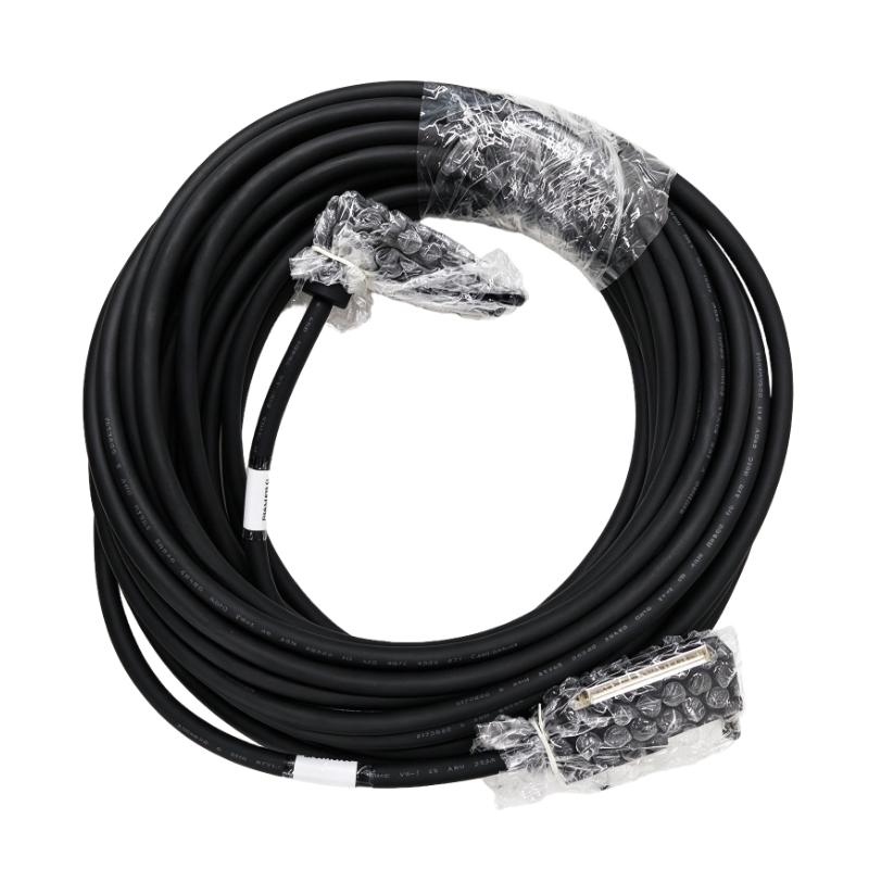
Foxboro P0916FN Terminal Cable Troubleshooting Guide (Signal Fault Diagnosis & Repair)
Foxboro P0916FN Terminal Cable Troubleshooting for Intermittent DCS Signals
Foxboro P0916FN Terminal Cable troubleshooting should begin with the signal path rather than immediate replacement of the cable or DCS I/O module. Intermittent signals are frequently caused by loose termination, conductor damage, connector contact problems, or incorrect signal assignment.
When a DCS operator reports that one process signal is unstable, the key question is whether the signal changes at the field device, at the terminal, at the cable output, or only after reaching the I/O channel.
This makes Fault Diagnosis a matter of signal tracing.
Foxboro P0916FN Terminal Cable Fault Symptoms and Initial Diagnosis
Typical Foxboro P0916FN cable faults can appear as:
- Intermittent process values
- Loss of a discrete signal
- Signal fluctuation
- I/O channel diagnostic alarm
- Signal returning after cabinet movement
- Communication or instrumentation fault after maintenance
The timing of the fault provides useful information.
For example:
Fault appears when cable moves → suspect mechanical connection
Fault appears during vibration → inspect termination
Fault occurs when nearby equipment starts → investigate electrical interference
Fault appears immediately after replacement → verify cable identification and pin assignment
This initial classification prevents random component replacement.
Foxboro P0916FN Terminal Cable Continuity Fault Diagnosis
When a P0916FN cable is suspected, a continuity test is useful, but it should not be the only test.
A conductor may show continuity when stationary but fail under movement.
A practical test can therefore include:
Continuity Test
      ↓
Insulation / Short Test
      ↓
Connector Inspection
      ↓
Controlled Cable Movement
      ↓
Signal Monitoring
Suppose a conductor measures normally at 0.3 Ω during a static test but the signal becomes unstable when the cable is flexed. That behavior suggests a mechanical conductor or connector problem rather than a DCS configuration problem.
Testing should be performed only under appropriate isolation and maintenance procedures.
Foxboro P0916FN Terminal Cable Intermittent Signal Case Study
In one DCS maintenance case, an operator reported that a process indication occasionally dropped to zero for approximately one second before returning to normal.
The initial suspicion was the field transmitter.
However, the transmitter output remained stable during the event.
The engineering team then monitored the signal at different points.
Observed condition:
| Measurement Point | Normal Condition | During Fault |
|---|---|---|
| Field transmitter | Stable | Stable |
| Terminal point | Stable | Intermittent |
| DCS input | Stable | Signal lost |
The investigation focused on the cable and terminal connection.
A loose termination was found near the cabinet terminal strip. After the termination was corrected, the signal remained stable during extended operation.
The DCS I/O module did not require replacement.
Foxboro P0916FN Terminal Cable Open-Circuit and High-Resistance Faults
A partially broken conductor can produce a more difficult failure pattern than a completely open circuit.
A completely open cable usually creates an obvious signal loss.
A high-resistance connection may instead cause:
- Reduced signal level
- Intermittent readings
- Increased measurement error
- Faults that occur only under vibration
For this reason, engineers should compare the measured electrical condition against expected signal behavior.
For a current-loop application, for example, a technician may observe a normal signal under static conditions but a significant change when the cable connection is disturbed.
The troubleshooting objective is to determine whether the abnormality originates from:
Field instrument → terminal → P0916FN cable → I/O connection
rather than assuming the final I/O value represents the source of the problem.
Foxboro P0916FN Terminal Cable Shielding and Noise Troubleshooting
Electrical interference should be considered when a signal becomes noisy rather than simply disappearing.
Symptoms may include:
- Rapid signal fluctuation
- Random spikes
- Periodic interference
- Faults synchronized with motor operation
A useful diagnostic comparison is to correlate the signal disturbance with nearby equipment.
For example, if an instrumentation signal becomes unstable whenever a large motor starts, inspect cable routing, shielding, grounding, and proximity to high-power conductors.
In one field investigation, an analog signal showed periodic fluctuations at approximately the same time a variable-speed drive accelerated. The cable continuity was normal. The eventual issue was excessive exposure to electrical noise caused by cable routing.
Moving the instrumentation cable away from the drive output wiring significantly reduced the signal disturbance.
Foxboro P0916FN Terminal Cable Wrong-Connection Fault Diagnosis
Incorrect termination is another important Fault Diagnosis category, especially after cabinet modification.
A wrong connection may produce:
- Correct-looking continuity
- Incorrect process value
- Crossed signals
- Unexpected actuator operation
- DCS point mismatch
The correct diagnostic method is to compare the complete identification chain:
DCS Point
   ↓
I/O Channel
   ↓
Terminal Number
   ↓
Cable Identifier
   ↓
Field Device
If one element does not match the approved drawing, stop the investigation there and verify the physical wiring.
This method is much safer than changing DCS software addresses simply to make the displayed signal appear correct.
Foxboro P0916FN Terminal Cable Connector Fault Troubleshooting
Connector problems can create intermittent faults that disappear after a restart or cabinet inspection.
Inspect for:
- Bent contacts
- Loose locking hardware
- Contamination
- Mechanical stress
- Damaged housing
- Poor strain relief
A connector should be inspected both visually and mechanically.
If a signal changes when the connector is carefully manipulated under safe test conditions, the connection becomes a strong fault candidate.
However, avoid using uncontrolled physical movement as a permanent test method. The objective is to reproduce the failure safely and then correct the mechanical problem.
Foxboro P0916FN Terminal Cable Repair Verification
After repairing a suspected cable fault, reproduce the original operating conditions.
If the original problem occurred during machine vibration, test under representative vibration.
If it appeared during motor startup, monitor the signal during motor startup.
If it appeared after several hours of operation, perform an extended observation rather than declaring the repair complete after a five-minute test.
A useful repair record includes:
- Original symptom
- Root cause
- Cable identification
- Corrective action
- Electrical measurements
- Final verification result
This information becomes valuable for future Foxboro DCS maintenance.
Foxboro P0916FN Terminal Cable Fault Diagnosis Conclusion
Foxboro P0916FN Terminal Cable troubleshooting should follow the physical signal path and use measurable evidence to isolate the failure.
Intermittent signals, open circuits, high-resistance connections, connector problems, shielding issues, and incorrect termination can all create symptoms that initially appear to be DCS hardware failures.
A disciplined Foxboro P0916FN Fault Diagnosis process compares the field signal, terminal condition, cable continuity, connector integrity, and DCS input before replacing expensive control-system hardware. This approach reduces unnecessary downtime and provides a more reliable basis for terminal cable repair and maintenance.