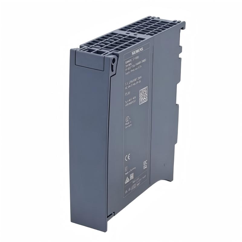
Siemens 6ES7556-1AA00-0AB0 Technology Module Installation Guide (Setup & Commissioning)
Siemens 6ES7556-1AA00-0AB0 Technology Module Installation Guide for S7-1500 Motion and Process Applications
Siemens 6ES7556-1AA00-0AB0 Technology Module installation should begin with application requirements, hardware compatibility, signal wiring, and System Configuration rather than simply mounting the module in the PLC rack. Technology modules interact closely with the CPU, field signals, and application program, so an incorrect configuration can produce faults even when the hardware is installed correctly.
The 6ES7556-1AA00-0AB0 is used within the SIMATIC S7-1500 technology-oriented automation environment. Its installation should therefore be treated as part of a complete control architecture:
S7-1500 CPU → Technology Module → Field Signals → Technology Function → PLC Application
For commissioning work, engineers should verify the exact module function, supported technology functions, firmware requirements, wiring arrangement, and applicable Siemens documentation for the actual project.
Siemens 6ES7556-1AA00-0AB0 Technology Module Application Planning
Before the Siemens 6ES7556-1AA00-0AB0 is installed, define what technology function the module is expected to perform.
The planning stage should identify:
- Required technology function
- Connected field devices
- Signal characteristics
- CPU and firmware environment
- Required engineering software
- Module addressing
- Diagnostic requirements
A useful commissioning document contains at least:
| Engineering Item | Verification |
|---|---|
| CPU | Compatible S7-1500 CPU |
| Technology module | Correct 6ES7556-1AA00-0AB0 identification |
| Firmware | Compatible project version |
| Field signals | Correct device and signal type |
| Hardware configuration | Correct module position |
| PLC program | Correct technology function mapping |
This preparation is especially important when replacing an existing module. A physically compatible replacement does not automatically mean that the stored hardware configuration and technology parameters are correct.
Siemens 6ES7556-1AA00-0AB0 Hardware Installation and Module Setup
The Siemens 6ES7556-1AA00-0AB0 Setup should be completed with the PLC rack de-energized according to the site's electrical safety procedure.
Before installation, inspect:
- Mounting rail condition
- Module housing
- Backplane interface
- Front connector
- Terminal wiring
- Cabinet cleanliness
A practical installation sequence is:
Application Review
       ↓
Hardware Compatibility Check
       ↓
Module Installation
       ↓
Front Connector Installation
       ↓
Field Wiring Verification
       ↓
Hardware Configuration
Do not force the module into position. The backplane connection should engage correctly without excessive mechanical pressure.
After mounting, inspect the neighboring modules as well. A poorly seated neighboring component or damaged connector can sometimes create symptoms that initially appear to originate from the technology module.
Siemens 6ES7556-1AA00-0AB0 Wiring Installation Guide
The wiring arrangement depends on the technology function and connected field equipment. The actual terminal assignment should always be taken from the documentation applicable to the specific module configuration.
Before applying power, verify:
- Terminal assignment
- Signal polarity
- Reference potential
- Shielding
- Cable identification
- External supply voltage
- Protective grounding
For signal-sensitive applications, separate low-level technology signals from high-power motor and switching circuits where practical.
A field wiring review can follow this logic:
Field Device
     ↓
Cable Identification
     ↓
Terminal Verification
     ↓
Signal Reference Check
     ↓
Shielding / Grounding Check
     ↓
Technology Module
One useful field habit is to verify the signal at the module terminal instead of checking only at the field device. A sensor can produce the expected signal while a damaged or incorrectly terminated cable prevents that signal from reaching the module.
Siemens 6ES7556-1AA00-0AB0 System Configuration and Parameter Setup
After physical installation, configure the Siemens 6ES7556-1AA00-0AB0 in the appropriate S7-1500 engineering project.
The System Configuration should be checked for:
- Correct module selection
- Correct rack position
- Hardware identification
- Firmware compatibility
- Address assignment
- Technology parameters
- Diagnostic settings
Do not assume that parameters from another technology module can simply be copied across.
A better engineering approach is:
Identify function → Verify hardware → Configure parameters → Download → Check diagnostics → Test function
After downloading the configuration, compare the online hardware status with the physical rack. This catches wrong module selection and rack-position errors before they become confusing process faults.
Siemens 6ES7556-1AA00-0AB0 Technology Function Commissioning
Siemens 6ES7556-1AA00-0AB0 Commissioning should start with a controlled test rather than immediately running the complete machine cycle.
First confirm:
- Module recognized correctly
- No active hardware diagnostic fault
- Required field signals are present
- Technology parameters are accepted
- CPU is operating normally
Then perform a controlled functional test.
For a technology application involving a measured process value, for example, compare:
| Test Point | Expected Result |
|---|---|
| Field device | Valid signal |
| Module input/status | Signal detected |
| PLC technology function | Correct processing |
| Program status | Expected state |
| HMI/process response | Correct indication |
The objective is to verify the complete signal and control path, not simply confirm that the module appears online.
Siemens 6ES7556-1AA00-0AB0 Commissioning Case Study
During the commissioning of an S7-1500 machine, the technology function did not respond as expected even though the CPU and technology module were both online.
The engineering team initially checked the field wiring and found:
- Field supply: approximately 24 VDC
- Field device output: present
- Module status: operational
- CPU: RUN
Because the hardware appeared healthy, the investigation moved to the System Configuration.
The configured technology parameters did not match the actual application requirements. After correcting the configuration and downloading the validated project, the technology function responded correctly.
The important lesson was that an online module status does not prove that the technology function has been configured correctly. Hardware diagnostics and functional commissioning are separate checks.
Siemens 6ES7556-1AA00-0AB0 Technology Module Performance Validation
After initial commissioning, test the module under representative operating conditions.
Validation should include:
- Normal operating range
- Startup sequence
- Maximum expected operating condition
- Repeated cycles
- Alarm and diagnostic behavior
Monitor the relevant process values instead of relying only on the absence of alarms.
For example, if the technology function controls a process variable, record the commanded and actual values during acceleration, steady-state operation, and shutdown.
A useful commissioning record contains:
Initial condition → Configuration → Test value → Observed response → Final parameter
This makes later Troubleshooting much easier.
Siemens 6ES7556-1AA00-0AB0 Installation Maintenance Recommendations
After commissioning, preserve the validated configuration and wiring documentation.
Maintenance personnel should retain:
- Hardware configuration
- PLC project backup
- Technology parameters
- Wiring drawings
- Firmware information
- Commissioning records
When replacing the Siemens 6ES7556-1AA00-0AB0, compare the replacement hardware with the original project before powering the system.
A technology module should be maintained as part of the complete S7-1500 architecture rather than as an isolated component.