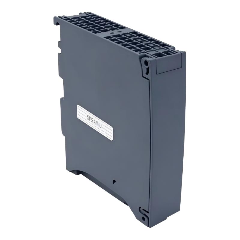
Siemens 6ES7556-1AA00-0AB0 Technology Module Troubleshooting Guide (Fault Diagnosis & Repair)
Siemens 6ES7556-1AA00-0AB0 Technology Module Troubleshooting for Configuration and Signal Faults
Siemens 6ES7556-1AA00-0AB0 Technology Module Troubleshooting should distinguish between hardware faults, field-signal problems, configuration errors, and technology-function problems. A module can be correctly powered and recognized by the CPU while its intended technology function remains incorrectly configured.
A practical Fault Diagnosis path is:
Symptom → Diagnostic Status → Field Signal → Hardware Configuration → Technology Parameters → Functional Test
This prevents engineers from replacing the module before establishing where the failure actually occurs.
Siemens 6ES7556-1AA00-0AB0 Technology Module Fault Symptoms
Typical symptoms may include:
- Technology function does not start
- Unexpected diagnostic status
- Incorrect process response
- Invalid or unstable technology values
- CPU reports a module-related diagnostic event
- Function works in manual testing but fails in automatic operation
The timing of the fault is important.
Ask:
- Did the problem occur immediately after installation?
- Did it appear after a PLC project download?
- Does it occur only under a particular process condition?
- Does the fault affect one function or the entire module?
These questions reduce the diagnostic area before any hardware is removed.
Siemens 6ES7556-1AA00-0AB0 Configuration Fault Diagnosis
A configuration mismatch is one of the first areas to investigate when a recently installed module fails to perform correctly.
Compare:
Physical hardware ↔ Engineering project ↔ Online diagnostic status
Check:
- Exact module identification
- Rack position
- Firmware compatibility
- Parameter values
- Address assignment
- Technology object or function configuration where applicable
If the physical module is correct but the engineering project contains a different hardware configuration, the system may produce diagnostic information or unexpected function behavior.
Avoid changing multiple parameters simultaneously. Record the original configuration before making corrections.
Siemens 6ES7556-1AA00-0AB0 Field Signal Troubleshooting
When the module receives external signals, troubleshoot the signal path before condemning the hardware.
Check the signal at three points:
Field Device
     ↓
Cable / Terminal
     ↓
6ES7556-1AA00-0AB0
For an electrical signal, compare the expected value with the measured value.
Example:
- Field output: 24.1 VDC
- Cabinet terminal: 24.0 VDC
- Module terminal: 0 VDC
The measurement immediately identifies the wiring section as the likely fault location.
If the signal reaches the module correctly but the technology function reports an abnormal condition, continue with configuration and module diagnostics.
Siemens 6ES7556-1AA00-0AB0 Technology Function Failure Case Study
A machine reported that its technology-controlled operation stopped intermittently.
The maintenance team initially suspected the 6ES7556-1AA00-0AB0 because the failure appeared during operation rather than startup.
The diagnostic investigation showed:
- CPU remained in RUN
- Module remained recognized
- Field signal remained present
- Fault appeared only when the machine entered a specific operating mode
The engineering team compared the technology parameters used during the failed operating mode with the validated commissioning values.
One application parameter had been modified during a previous maintenance intervention.
After restoring the validated parameter set and repeating the operating cycle, the technology function returned to stable operation.
The lesson is important: intermittent technology faults can originate from parameter changes even when the module itself remains healthy.
Siemens 6ES7556-1AA00-0AB0 Diagnostic Status Troubleshooting
When a diagnostic event occurs, record the exact diagnostic information before resetting the PLC.
Capture:
- Diagnostic message
- Module status
- CPU operating state
- Time of occurrence
- Process condition
- Relevant signal values
The same alarm occurring during startup has a different diagnostic meaning from the same alarm appearing only after several hours of operation.
For intermittent faults, a simple maintenance log can be valuable:
| Time | Machine State | Module Status | Signal | Fault |
|---|---|---|---|---|
| 10:05 | Startup | Normal | Normal | None |
| 11:42 | Automatic | Diagnostic | Normal | Function stopped |
| 11:45 | Reset | Normal | Normal | Recovered |
This allows engineers to correlate the failure with machine conditions.
Siemens 6ES7556-1AA00-0AB0 Signal Instability Fault Analysis
If the technology module receives an unstable process signal, investigate the field side before adjusting control parameters.
Possible causes include:
- Electrical interference
- Loose terminals
- Damaged cable
- Poor shielding
- Unstable field device
- Incorrect signal reference
For example, a process value that normally remains around 50.0 units but repeatedly jumps between 49.5 and 50.8 units during motor operation should trigger an EMC and wiring investigation.
Changing technology parameters may hide the symptom without removing the source.
Siemens 6ES7556-1AA00-0AB0 Hardware Failure Troubleshooting
Only after field wiring and configuration have been verified should the possibility of module hardware failure become a primary suspect.
Useful evidence includes:
- Persistent module diagnostics
- Failure affecting the same hardware channel
- Correct field signal at the terminal
- Correct configuration
- Failure remaining after controlled software verification
If replacement becomes necessary, record the original module status and configuration first.
After installing another module, verify:
- Hardware recognition
- Configuration compatibility
- Parameter download
- Diagnostic status
- Technology function
- Actual machine operation
Siemens 6ES7556-1AA00-0AB0 Repair and Recovery Verification
A successful repair must reproduce the operating condition that originally generated the fault.
For example, if the fault appeared during a high-speed production cycle, a low-speed manual test is insufficient.
Repeat:
- Original operating mode
- Relevant process condition
- Full machine sequence
- Multiple cycles
Compare the results with the original diagnostic record.
A useful repair criterion is:
Original fault reproduced → Root cause identified → Corrective action completed → Original condition repeated → Fault absent
This is more reliable than simply confirming that the module has returned to an online state.
Siemens 6ES7556-1AA00-0AB0 Fault Diagnosis Best Practices
Effective Siemens 6ES7556-1AA00-0AB0 Troubleshooting depends on separating four diagnostic layers:
Field signal → Hardware → Configuration → Technology function
When a problem appears, work through these layers systematically. Do not assume that a technology module is defective simply because the machine function associated with it has stopped.
For maintenance teams, the most useful information is often the combination of exact diagnostic status, measured signal values, operating conditions, and configuration history. This provides a much stronger basis for Fault Diagnosis and Repair than alarm resets or immediate hardware replacement.