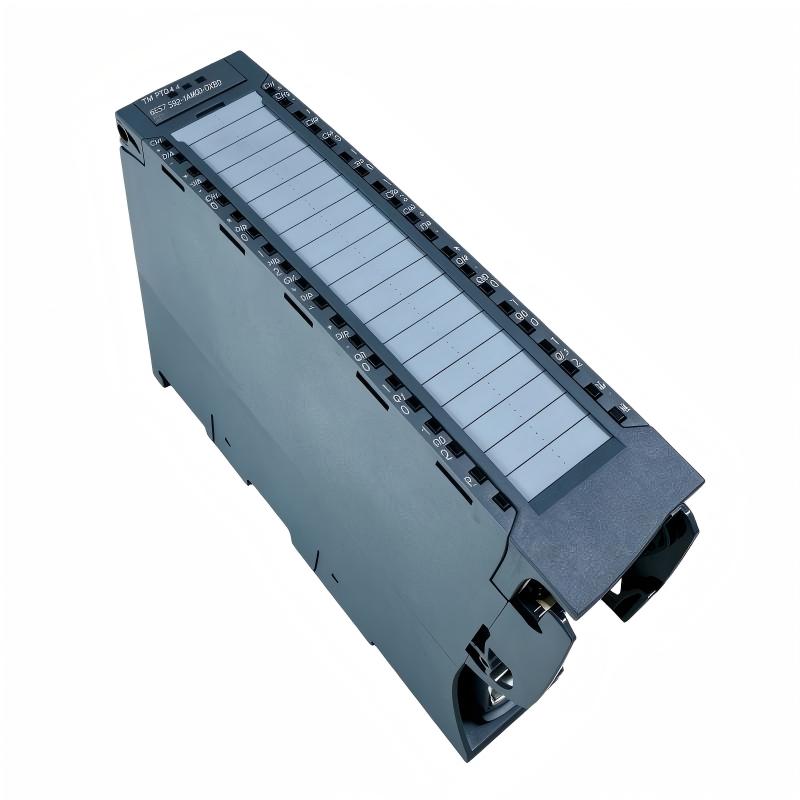
Siemens 6ES7553-1AA00-0AB0 Interface Module Installation Guide (System Setup & Commissioning)
Siemens 6ES7553-1AA00-0AB0 Interface Module Installation Guide for S7-1500 System Integration
The Siemens 6ES7553-1AA00-0AB0 Interface Module installation should be approached as a system-integration task: verify the module position, backplane connection, partner module compatibility, hardware configuration, and diagnostic status before commissioning the PLC station. An interface module can be mechanically installed correctly yet still fail to operate if the configured hardware arrangement does not match the physical system.
For S7-1500 installations, the interface between system components must remain electrically and mechanically reliable. This makes connector seating, module alignment, configuration consistency, and diagnostic verification important parts of the Installation Guide.
Siemens 6ES7553-1AA00-0AB0 Interface Module Installation Planning
Before installing the Siemens 6ES7553-1AA00-0AB0, identify its exact position in the planned S7-1500 architecture and verify the associated modules.
The preparation checklist should include:
- Confirming the complete order number
- Checking the intended rack or station arrangement
- Verifying compatible partner modules
- Reviewing the project hardware configuration
- Checking the required firmware environment
- Preparing commissioning and diagnostic records
A useful pre-installation table is:
| Check | Engineering Action |
|---|---|
| Module identification | Confirm 6ES7553-1AA00-0AB0 |
| Physical position | Match cabinet layout |
| Partner hardware | Verify compatibility |
| Backplane interface | Inspect for contamination or damage |
| Configuration | Compare project with actual hardware |
| Documentation | Prepare wiring and hardware records |
This step is particularly important when the interface module is being installed as a replacement.
Siemens 6ES7553-1AA00-0AB0 Hardware Setup and Mounting
The physical Setup should be completed with the relevant equipment safely isolated.
Inspect the mounting area before installing the module. Look for damaged connectors, loose mounting components, foreign material, or signs of previous overheating.
The installation sequence can be organized around the hardware rather than a generic step-by-step procedure:
Rack Condition
      ↓
Module Position
      ↓
Mechanical Engagement
      ↓
Backplane Connection
      ↓
Connector Verification
      ↓
Power-Up Inspection
The 6ES7553-1AA00-0AB0 should engage with the rack and adjacent system components without excessive force. A partially engaged interface connection can produce intermittent communication or module-recognition problems that are difficult to reproduce.
After installation, inspect the neighboring modules as well. An interface fault can sometimes originate from the connection between adjacent components rather than from the interface module itself.
Siemens 6ES7553-1AA00-0AB0 Interface Connection Verification
A reliable interface depends on a clean and mechanically secure connection.
Before commissioning, inspect:
- Module seating
- Connector engagement
- Backplane contacts
- Mechanical locking
- Cable connections where applicable
- Cabinet grounding arrangement
Do not use an electrical measurement alone to determine whether a mechanical interface is correctly seated. Physical inspection is equally important.
During maintenance, avoid touching exposed contacts unnecessarily. Contamination from dust, oil, or handling can affect low-level electrical connections over time.
Siemens 6ES7553-1AA00-0AB0 System Configuration and Hardware Engineering
The Siemens 6ES7553-1AA00-0AB0 must be represented correctly in the PLC engineering project.
The System Configuration should be compared against the actual installation for:
- Module order
- Module position
- Hardware identification
- Firmware compatibility
- Station configuration
- Diagnostic settings
A practical engineering sequence is:
Physical identification → Hardware catalog selection → Rack placement → Configuration validation → Download → Online diagnostic check
If the physical module and project configuration do not correspond, the CPU may report a configuration-related diagnostic condition.
For replacement work, compare the previous project backup with the new hardware arrangement before making changes. This is usually more reliable than rebuilding the configuration from memory.
Siemens 6ES7553-1AA00-0AB0 PLC Commissioning and Validation
Commissioning should begin with hardware recognition before testing the complete application.
First confirm:
- CPU reaches the expected operating state
- Interface module is recognized
- No relevant diagnostic fault is active
- Associated modules are correctly detected
Then verify the communication or system function supported by the installed architecture.
A practical validation sequence is:
Power-Up
   ↓
Hardware Recognition
   ↓
Diagnostic Status
   ↓
System Communication
   ↓
Application Test
   ↓
Extended Operation
Avoid moving directly from power-up to a full production cycle. If a problem occurs, staged commissioning makes it easier to determine whether the failure appeared during hardware initialization or application operation.
Siemens 6ES7553-1AA00-0AB0 Commissioning Case Study
During an S7-1500 system expansion, an interface module was installed and the PLC station was powered up. The CPU entered a diagnostic condition even though the module appeared physically undamaged.
The engineering team checked the system in three layers.
Physical inspection
- Module housing: normal
- Mounting: secure
- Connector: visually intact
Hardware configuration
- CPU configuration: correct
- Interface module position: incorrect compared with the physical rack arrangement
Online verification
- Diagnostic condition corresponded with the hardware configuration mismatch
After correcting the project configuration and downloading the validated hardware arrangement, the station initialized normally.
The important commissioning lesson was that an interface module fault indication does not automatically mean physical hardware failure. The actual hardware arrangement must always be compared with the engineering project.
Siemens 6ES7553-1AA00-0AB0 Installation Validation for Industrial Operation
After successful startup, perform a controlled application test.
Monitor:
| Validation Area | What to Observe |
|---|---|
| Module status | Normal operating state |
| CPU diagnostics | No unexpected hardware events |
| Connected modules | Correct recognition |
| System communication | Stable operation |
| Application sequence | Correct response |
For an intermittent installation problem, extend the test beyond a single startup. Vibration, thermal cycling, and repeated machine operation can reveal connection problems that remain invisible during a short commissioning test.
Record the final hardware configuration and validated project version for maintenance use.
Siemens 6ES7553-1AA00-0AB0 Interface Module Installation Best Practices
For reliable operation, maintenance teams should:
- Keep the module identification recorded
- Maintain an updated rack layout
- Back up the validated PLC project
- Inspect connectors during scheduled maintenance
- Record hardware changes
- Compare replacement hardware with the original configuration
The Siemens 6ES7553-1AA00-0AB0 Interface Module should be treated as part of the complete PLC architecture. Careful Installation, System Configuration, and Commissioning reduce the risk of configuration mismatches and intermittent interface faults.