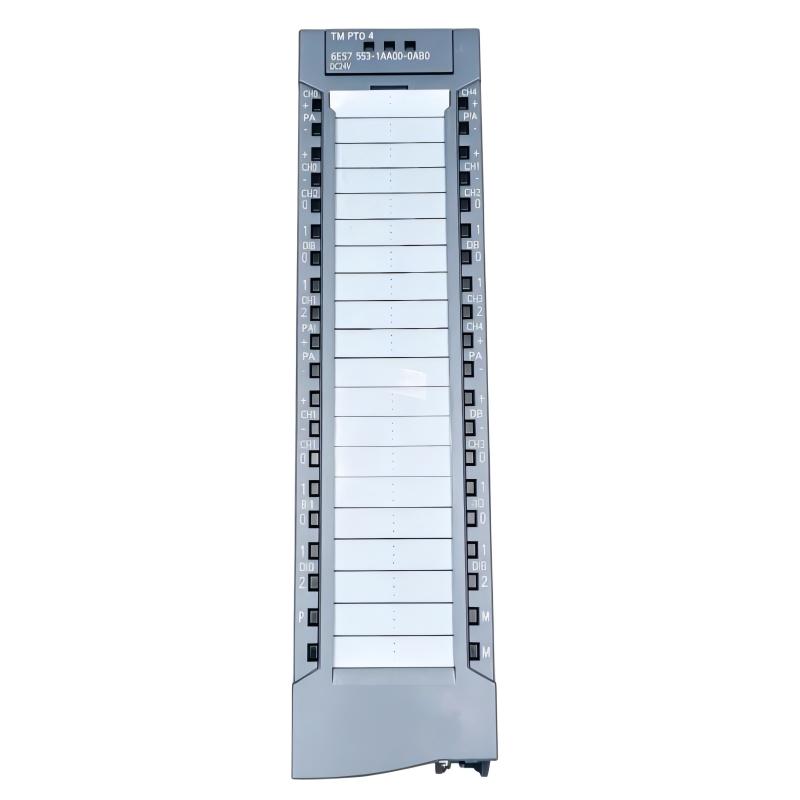
Siemens 6ES7553-1AA00-0AB0 Interface Module Troubleshooting Guide (Fault Diagnosis & Repair)
Siemens 6ES7553-1AA00-0AB0 Interface Module Troubleshooting for PLC Communication and Hardware Faults
Siemens 6ES7553-1AA00-0AB0 Interface Module Troubleshooting should start by determining whether the problem is caused by physical connection, hardware configuration, an associated module, or the interface module itself. A module that reports an error is not necessarily the failed component.
A practical Fault Diagnosis method follows the architecture:
CPU → Interface Module → Associated Hardware → Application
The most useful evidence is the diagnostic status combined with the exact point at which the system stops operating normally.
Siemens 6ES7553-1AA00-0AB0 Interface Module Fault Symptoms
Common symptoms may include:
- Module not recognized
- Hardware configuration diagnostic
- Unexpected station fault
- Loss of communication between system components
- Intermittent module status
- Application unavailable after PLC startup
First determine whether the problem appeared:
- Immediately after installation
- Following a configuration download
- After cabinet maintenance
- During normal production
- Only after extended operation
The timing significantly narrows the troubleshooting path.
Siemens 6ES7553-1AA00-0AB0 Module Recognition Fault Diagnosis
If the Siemens 6ES7553-1AA00-0AB0 is not recognized, start with physical installation.
Check:
- Module seating
- Rack position
- Backplane interface
- Associated hardware
- Hardware configuration
- Diagnostic information
A useful comparison is:
Physical Rack
     ↕
Engineering Project
     ↕
Online Hardware Status
All three should describe the same system.
If the physical module is correctly installed but the engineering project shows a different module arrangement, correct the configuration before replacing hardware.
Siemens 6ES7553-1AA00-0AB0 Hardware Configuration Fault Troubleshooting
A configuration mismatch can occur after a PLC project is restored from an older machine backup.
Typical causes include:
- Different hardware arrangement
- Incorrect module position
- Changed firmware environment
- Incomplete project update
- Incorrect module selection
For Fault Diagnosis, compare the online diagnostic information with the physical rack and the project configuration.
Do not modify several hardware parameters simultaneously. Make one controlled correction, download the validated configuration, and then observe the resulting diagnostic state.
Siemens 6ES7553-1AA00-0AB0 Intermittent Interface Fault Analysis
An intermittent interface fault requires a different diagnostic approach from a permanent configuration error.
Useful observations include:
- Fault frequency
- Machine vibration
- Cabinet temperature
- Power-cycle behavior
- Module status before and after failure
For example, if the interface operates normally for several hours and then loses communication while a nearby machine is vibrating, inspect the mechanical connection before assuming an electronic failure.
A fault that disappears after power cycling should not automatically be considered resolved. The original operating condition should be reproduced before closing the maintenance case.
Siemens 6ES7553-1AA00-0AB0 Connection Fault Case Study
A production system experienced an intermittent interface-related diagnostic event approximately once every several hours.
The first diagnostic record showed:
- CPU: RUN before event
- Interface status: intermittent
- Application: temporarily stopped
- Power supply: stable
The engineering team inspected the physical installation and found that the interface connection had slight mechanical movement caused by cabinet vibration.
After securing the affected connection and checking the surrounding mounting hardware, the system was operated through repeated production cycles.
The interface fault did not return.
The diagnostic lesson is straightforward: when a PLC interface fault is intermittent, the physical connection and environmental conditions should be investigated alongside the software diagnostics.
Siemens 6ES7553-1AA00-0AB0 Communication Fault Troubleshooting
If the interface module is recognized but the associated system function does not operate correctly, check the communication path rather than immediately replacing the interface hardware.
Review:
- Module diagnostic status
- Partner module status
- Configuration consistency
- Relevant cable connections
- Application communication logic
A useful diagnostic comparison is to determine whether the failure affects the complete interface or only one downstream function.
If multiple functions fail simultaneously, investigate the common interface path.
If only one function fails while the remainder of the system remains stable, investigate the associated field device, module, or application configuration.
Siemens 6ES7553-1AA00-0AB0 Power and Hardware Fault Diagnosis
If the interface module repeatedly enters a fault state, verify the power and hardware environment before declaring the module defective.
Check:
- PLC power supply status
- CPU diagnostic buffer
- Module recognition
- Backplane connection
- Adjacent module condition
Measure the relevant supply voltage using the manufacturer's specified test procedure and compare the result with the system requirements.
If the power supply remains stable while the same interface module consistently reports a hardware diagnostic condition under verified configuration, the probability of a module-related problem increases.
Siemens 6ES7553-1AA00-0AB0 Repair and Replacement Procedure
Hardware replacement should be based on diagnostic evidence.
Before replacing the Siemens 6ES7553-1AA00-0AB0:
- Save diagnostic information
- Back up the PLC project
- Record the existing hardware arrangement
- Verify field connections
- Confirm configuration compatibility
After replacement, do not assume the repair is complete when the module becomes visible online.
Repeat:
Hardware recognition → Configuration verification → Diagnostic check → Functional test → Production-cycle validation
This confirms that the corrective action addressed the actual failure.
Siemens 6ES7553-1AA00-0AB0 Fault Diagnosis Verification After Repair
The final repair test should reproduce the conditions associated with the original failure.
For a startup configuration fault, perform repeated power-up and initialization tests.
For an intermittent connection fault, perform extended operation under representative machine conditions.
For a communication fault, monitor the complete communication path during normal and peak operating conditions.
Record the final:
- Diagnostic status
- Hardware configuration
- Test conditions
- Corrective action
- Operating result
This creates a useful maintenance reference instead of simply recording "fault cleared."
Siemens 6ES7553-1AA00-0AB0 Interface Module Troubleshooting Best Practices
Effective Siemens 6ES7553-1AA00-0AB0 Troubleshooting depends on separating physical installation, System Configuration, associated hardware, and application behavior.
When a fault occurs, avoid immediately replacing the Interface Module. First determine whether the diagnostic evidence points to a physical connection, configuration mismatch, power condition, partner component, or actual hardware failure.
A disciplined Fault Diagnosis process makes PLC maintenance more predictable and reduces unnecessary replacement of functional Siemens automation hardware.