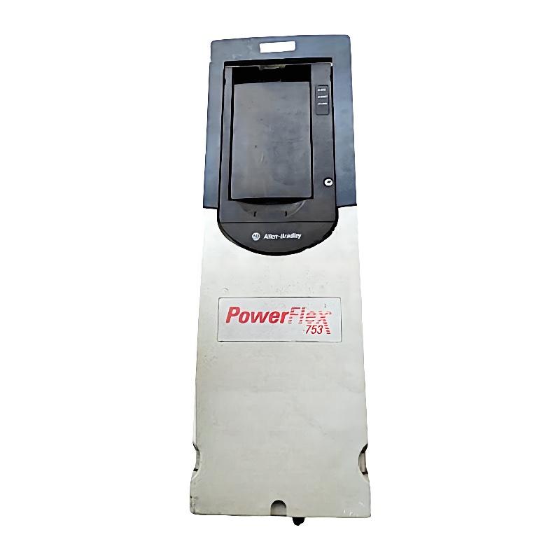
Allen Bradley 20F11NC2P1JA0NNNNN PowerFlex 753 AC Drive Installation Guide (Wiring & Commissioning)
Installation Overview of the Allen Bradley 20F11NC2P1JA0NNNNN
The Allen Bradley 20F11NC2P1JA0NNNNN is a PowerFlex 753 AC drive designed for industrial motor speed and torque control. It is used in applications that require adjustable motor operation, controlled acceleration and deceleration, and integration with automated control systems.
A successful installation involves more than mounting the drive and connecting the motor. Engineers should verify the drive's complete catalog configuration, input power requirements, motor ratings, control interface, protection settings, and installation environment before energizing the equipment.
The PowerFlex 753 supports flexible control and integration options, making it suitable for machinery such as pumps, fans, conveyors, mixers, and other variable-speed industrial equipment.
2. Pre-Installation Checks and Electrical Preparation
Before installing the 20F11NC2P1JA0NNNNN, compare the complete catalog number with the drive nameplate and project documentation. PowerFlex 753 products are available in different electrical and hardware configurations, so input voltage, current rating, enclosure arrangement, and installed options must be confirmed rather than inferred from the family name alone.
Review the following points:
Confirm that the drive's input voltage matches the plant power supply.
Verify that the drive current rating is suitable for the connected motor.
Check the motor nameplate for rated voltage, current, frequency, and speed.
Confirm the required braking and communication options.
Review the installation clearance and cooling requirements.
Prepare correctly rated circuit protection and grounding connections.
Ensure that the installation location meets the environmental requirements.
Disconnect and isolate the power source before electrical work. Follow the manufacturer's discharge-time instructions and verify that the DC bus voltage has reached a safe level before touching internal components.
3. PowerFlex 753 Mechanical Mounting and Ventilation
The drive should be installed in a location that allows adequate airflow and convenient access for inspection and maintenance.
During mounting:
Check the mounting surface for sufficient mechanical strength.
Verify the required orientation and clearances.
Ensure that cooling air passages are not obstructed.
Keep the drive away from excessive dust, moisture, and corrosive contaminants.
Provide sufficient space for power cables and control wiring.
Secure the drive according to the installation instructions for its specific frame and enclosure configuration.
Poor ventilation can cause excessive internal temperature and reduce drive reliability. Where multiple drives are installed in one cabinet, consider the total heat dissipation and cabinet cooling capacity.
4. Power Wiring, Motor Connections, and Grounding
Correct power wiring is essential for safe operation. The incoming supply, motor output, and protective earth connections must follow the wiring diagrams applicable to the installed PowerFlex 753 configuration.
Important installation practices include:
Connect the incoming three-phase supply to the designated input terminals.
Connect the motor conductors to the designated output terminals.
Establish a low-impedance protective grounding connection.
Use cables with suitable voltage and current ratings.
Separate motor power cables from low-level control and feedback wiring.
Apply appropriate shielding and cable termination practices where required.
Check terminal tightness using the specified torque values.
Do not connect the incoming power supply to the drive's motor output terminals. Verify motor rotation and phase sequence during controlled commissioning.
5. Control Wiring and Automation System Integration
The PowerFlex 753 can be integrated into a machine control system using its supported control interfaces and installed communication options. The exact available interfaces depend on the drive's configuration.
Before connecting the drive to a PLC or distributed control system, confirm:
The selected start/stop command source.
The speed reference source.
The control terminal assignments.
The installed communication adapter and network configuration.
The required feedback signals.
The drive's fault and status signal mapping.
For PLC-controlled operation, make sure the control program and drive parameters use consistent command and reference sources. A mismatch between local control, terminal control, and network control can prevent the drive from responding as expected.
6. Motor Data Entry and Initial Parameter Setup
Accurate motor data is necessary for correct drive operation. Enter the values from the motor nameplate rather than relying on generic factory settings.
Typical configuration items include:
Parameter group | Configuration purpose |
|---|---|
Motor nameplate data | Defines rated motor electrical characteristics |
Command source | Selects where start and stop commands originate |
Speed reference | Defines the source of the operating speed command |
Acceleration time | Controls the motor ramp-up period |
Deceleration time | Controls the motor ramp-down period |
Motor overload protection | Establishes suitable motor thermal protection |
Minimum and maximum frequency | Defines the permitted operating speed range |
Stop mode | Determines how the motor responds to a stop command |
Parameter numbers and available settings can vary with firmware and installed options. Use the applicable PowerFlex 753 programming documentation when entering or modifying parameters.
7. Commissioning Procedure for the PowerFlex 753
After installation and configuration, carry out commissioning in a controlled sequence.
Step 1: Inspect the installation
Check power terminals, grounding, control wiring, cabinet ventilation, and motor connections.
Step 2: Verify the supply
Confirm that the incoming voltage and phase configuration match the drive nameplate.
Step 3: Review motor parameters
Compare the entered motor data with the actual motor nameplate.
Step 4: Check the command and reference sources
Confirm whether the drive is controlled locally, through terminal signals, or through a network connection.
Step 5: Perform a controlled test run
Where the machine design permits, test the motor under a safe, unloaded or reduced-load condition.
Step 6: Confirm operating feedback
Monitor output frequency, motor current, speed response, and drive status.
Step 7: Test protective functions
Verify that relevant interlocks, emergency stop circuits, and fault responses operate according to the machine safety design.
8. Common Installation Issues and Corrective Actions
Installation issue | Possible cause | Recommended action |
|---|---|---|
Drive does not power up | Supply wiring or protection issue | Check incoming power and protective devices |
Motor does not start | Incorrect command source | Verify start command configuration |
Motor rotates in the wrong direction | Motor phase sequence or application setup | Follow the approved motor direction correction procedure |
Drive trips during acceleration | Excessive load or unsuitable ramp settings | Review load conditions and acceleration time |
Communication is unavailable | Network or adapter configuration mismatch | Verify installed adapter, address, and network settings |
Drive overheats | Restricted airflow or high ambient temperature | Inspect ventilation and cabinet cooling |
Motor speed is incorrect | Incorrect reference source or scaling | Check speed reference and related parameters |
Illustrative commissioning case: A conveyor system is upgraded with a PowerFlex 753 drive. During the initial test, the PLC indicates that a start command has been issued, but the motor remains stopped. The technician checks the drive status and discovers that the selected command source does not match the PLC control arrangement. After correcting the command-source configuration and confirming the network or terminal interface settings, the drive responds correctly to the PLC command.