Allen Bradley 20AD065A0AYNANC0 PowerFlex 70 AC Drive Installation Guide (Wiring & Commissioning)
PowerFlex 70 AC Drive Installation Overview
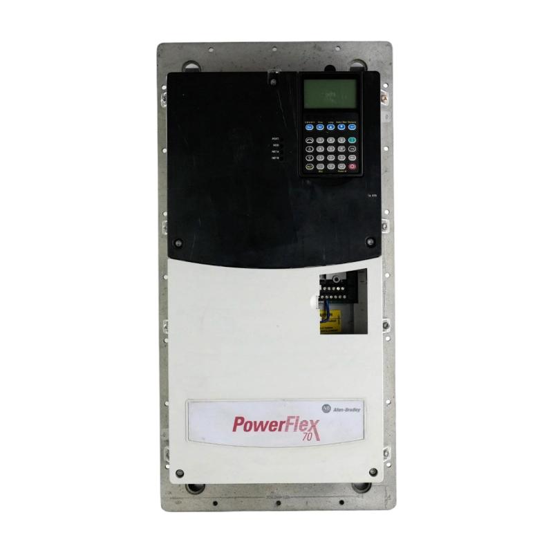
The Allen Bradley 20AD065A0AYNANC0 is a PowerFlex 70 AC drive designed for adjustable-speed control of three-phase AC motors. It is used in industrial applications where controlled acceleration, deceleration, motor speed regulation, and integration with automation systems are required.
Typical applications include conveyors, pumps, fans, mixers, material-handling equipment, and general-purpose industrial machinery.
Successful installation requires careful verification of the drive's electrical configuration, motor compatibility, grounding arrangement, control wiring, and operating environment. Before beginning work, check the complete catalog number and drive nameplate to confirm the actual voltage class, current rating, enclosure configuration, and installed options.
2. Pre-Installation Inspection and Electrical Requirements
Before mounting the 20AD065A0AYNANC0, inspect the drive for shipping damage and verify that its nameplate information matches the project requirements.
Pay particular attention to:
Incoming supply voltage and phase configuration.
Drive output current rating and motor full-load current.
Motor rated voltage, frequency, speed, and power.
Required input protection and disconnecting equipment.
Control interface and communication requirements.
Installation altitude and ambient temperature.
Cabinet ventilation and environmental protection.
The drive must be installed in accordance with the electrical requirements for its specific configuration. Do not select circuit breakers, fuses, or cable sizes based only on the PowerFlex 70 product family name.
Before working on the drive, disconnect all power sources, follow lockout/tagout procedures, and allow the DC bus to discharge for the period specified in the applicable installation manual. Verify the DC bus voltage with an appropriately rated meter before touching internal components.
3. Mechanical Mounting and Cabinet Preparation
The PowerFlex 70 should be mounted on a stable surface with sufficient clearance for cooling airflow and maintenance access.
A suitable installation location should provide:
Adequate ventilation around the drive.
Protection from conductive dust and corrosive contaminants.
A stable operating temperature.
Sufficient space for power and control cable routing.
Access to the keypad and status indicators.
Appropriate separation from sensitive low-voltage equipment.
Check the mounting orientation and clearance requirements for the actual drive enclosure. If the drive is installed inside a control cabinet, calculate the cabinet's heat dissipation requirements rather than relying only on the drive's physical dimensions.
4. Power Wiring and Motor Connection Procedure
Correct wiring of the incoming power and motor output circuits is essential for safe operation.
The installation process should include:
Identify the incoming supply terminals using the drive's wiring diagram.
Connect the incoming power conductors to the designated input terminals.
Connect the motor conductors to the designated output terminals.
Establish the required protective earth connection.
Verify cable insulation and conductor sizing.
Check terminal tightness using the specified torque values.
Inspect the completed wiring before energizing the drive.
Never connect the incoming supply directly to the motor output terminals. Keep motor cables separated from control and feedback wiring where practical. Follow the manufacturer's recommendations for cable shielding, grounding, and electromagnetic interference reduction.
If the motor rotates in the wrong direction, correct the phase sequence only after the equipment has been safely stopped and isolated.
5. Control Terminal Wiring and PLC Integration
The PowerFlex 70 supports configurable control functions for industrial automation applications. Depending on the installed hardware and options, the drive can receive commands and references through control terminals or supported communication interfaces.
Before connecting the drive to a PLC, establish the control architecture.
Important configuration points include:
Start and stop command source.
Speed reference source.
Digital input assignments.
Analog input scaling, where used.
Fault relay and status signal assignments.
Communication interface settings.
Required interlocks and permissive conditions.
A common commissioning problem occurs when the PLC sends a valid start command but the drive is configured to accept commands from another source. Confirm that the selected command source matches the actual wiring or network arrangement.
6. Motor Parameters and Initial Drive Configuration
Enter the motor information according to the motor nameplate and the drive's parameter structure.
The initial setup should cover:
Configuration item | Purpose |
|---|---|
Motor rated voltage | Establishes the motor voltage reference |
Motor rated current | Supports appropriate motor protection and control |
Motor rated frequency | Defines the motor's nominal operating frequency |
Motor rated speed | Supports speed-related calculations |
Acceleration time | Determines the motor ramp-up period |
Deceleration time | Determines the motor ramp-down period |
Minimum frequency | Sets the lower operating speed limit |
Maximum frequency | Sets the upper operating speed limit |
Start command source | Selects the source of start and stop commands |
Speed reference source | Defines where the speed command originates |
Parameter numbers and available functions can vary with drive firmware and installed options. Use the correct PowerFlex 70 documentation when setting parameters.
7. PowerFlex 70 Startup and Commissioning Procedure
A controlled startup helps identify wiring and configuration errors before the drive is connected to normal production operation.
Step 1: Complete a visual inspection
Check grounding, cable routing, terminal connections, and cabinet ventilation.
Step 2: Verify the input supply
Confirm that the measured supply voltage is suitable for the drive nameplate.
Step 3: Review motor data
Compare all configured motor information with the motor nameplate.
Step 4: Confirm command and reference sources
Check whether the drive is intended to operate through local keypad control, terminal signals, or a PLC communication interface.
Step 5: Perform an initial motor test
Where the machine design permits, conduct a controlled test with the driven equipment in a safe condition.
Step 6: Monitor drive operation
Observe output frequency, motor current, speed response, and diagnostic indications.
Step 7: Test machine interlocks
Verify that stop commands, permissive conditions, and protective functions operate as designed before returning the equipment to service.
8. Common PowerFlex 70 Installation Problems
Symptom | Possible cause | Recommended action |
|---|---|---|
Drive does not power up | Incorrect supply connection or protective device issue | Check incoming power and circuit protection |
Motor does not start | Incorrect command source | Verify the start command configuration |
Motor speed is unstable | Incorrect reference scaling or signal interference | Check the reference signal and wiring |
Drive trips during acceleration | Excessive load or unsuitable acceleration settings | Inspect the mechanical load and ramp configuration |
Communication fails | Incorrect network settings or connection | Verify the installed communication interface |
Drive overheats | Restricted airflow or high ambient temperature | Inspect cabinet cooling and ventilation |
Motor rotates in the wrong direction | Incorrect motor phase sequence | Verify the motor connection under safe conditions |
Illustrative commissioning case: A material-handling conveyor is equipped with a PowerFlex 70 drive. During startup, the PLC sends a run command, but the motor does not respond. The technician checks the drive's command-source configuration and finds that the drive is still set to receive commands from the local control interface. After selecting the intended control source and verifying the PLC signal mapping, the motor starts correctly during the controlled test.