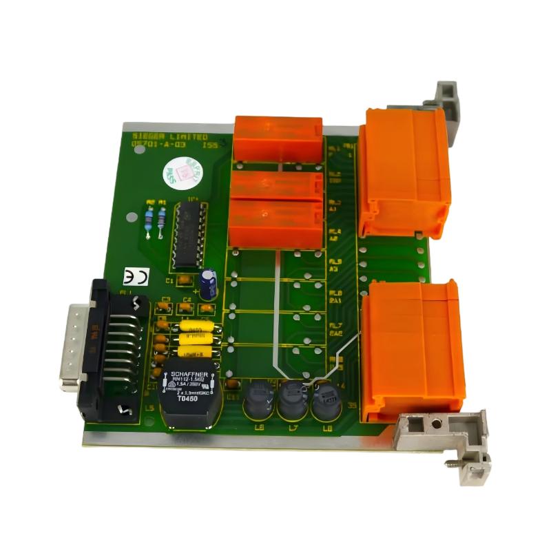
Honeywell 05701-A-0327 Single-Channel Control Card Installation Guide for System 57 Gas Detection Rack
Honeywell 05701-A-0327 single-channel control card installation issues are most often related to relay interface mismatch, backplane contact instability, or incorrect sensor drive configuration, rather than internal electronic failure. In System 57 gas detection racks, this card plays a hybrid role between signal processing and relay output execution, so both electrical and mechanical integrity are critical.
Honeywell 05701-A-0327 Control Card Role in System 57 Architecture
The Honeywell 05701-A-0327 is typically used as a relay/field interface or high-integrity control card in System 57 gas detection systems. Based on official System 57 architecture, a single channel consists of:
- Sensor drive module (catalytic or 4–20 mA input)
- Single-channel control card (signal processing + alarm logic)
- Relay / field interface card (alarm output switching)
The 05701-A-0327 is often deployed in configurations where A1, A2, and fault relay actions must be externally driven, especially in safety-critical gas detection loops.
In one LNG terminal upgrade, a false A2 alarm was traced not to the sensor or transmitter, but to unstable relay switching inside a partially seated 05701-A-0327 card, which intermittently changed contact state during compressor startup vibration.
Honeywell 05701-A-0327 Installation Preparation in Control Rack
Before installation, engineers must ensure the System 57 rack is mechanically and electrically stable.
Rack-Level Preconditions
- 19-inch or half-rack System 57 subrack properly grounded
- DC supply stable (typically 18–32 V DC)
- Backplane connectors clean and free of oxidation
- No mechanical deformation in card slot rails
Field experience shows that oxidized backplane contacts can increase relay chatter probability by introducing micro voltage instability in the control logic path.
Honeywell 05701-A-0327 Mechanical Installation and Wiring Logic
Unlike pure analog cards, the 05701-A-0327 directly affects alarm relay outputs, so mechanical seating quality directly influences safety behavior.
Installation Procedure (Field Logic)
- Align card carefully with rack guide rails
- Insert fully until locking mechanism engages
- Ensure no partial seating (critical failure mode)
- Tighten front locking screws to prevent vibration loosening
In a refinery gas monitoring system, a 0.2 mm misalignment caused intermittent relay switching during high-load motor starts. The system generated false “Fault” alarms every 15–20 minutes until reseating corrected the issue.
Electrical Interface Behavior
Once installed, the card performs:
- Continuous gas signal monitoring via control logic
- A1 / A2 threshold evaluation
- Relay activation for alarm outputs
- Fault detection and inhibit signaling
Relay outputs are sensitive to both supply voltage stability and EMI noise coupling, especially in shared cabinet environments with VFDs.
Honeywell 05701-A-0327 Commissioning Strategy (Field-Oriented)
Commissioning should focus on relay stability under dynamic industrial conditions, not just static signal validation.
Cold Start Validation
- Confirm Power LED stability
- Verify no Fault or Inhibit indication at startup
- Check baseline 4–20 mA sensor input consistency
Dynamic Alarm Simulation Test
During simulated gas input:
- Verify A1/A2 relay switching response time (<1 second typical)
- Confirm no relay chatter under stable signal
- Observe output stability during rapid signal transitions
In one offshore compressor station, relay outputs flickered only during startup transient current spikes. Investigation showed shared grounding between relay coil supply and motor starter circuits.
Full Load Stress Test
- Activate multiple channels simultaneously
- Monitor relay response under vibration and load variation
- Verify fault isolation between adjacent cards
After grounding separation in one chemical plant, relay noise dropped significantly and false alarm rate reduced to near zero.