Honeywell 05701-A-0329 Single-Channel Control Card Installation Guide for DCS and Gas Detection Systems
Honeywell 05701-A-0329 single-channel control card installation issues are often caused by improper card seating, unstable 24 V DC supply, or backplane contamination, rather than internal electronic faults. In industrial DCS or System 57 gas detection racks, even minor misalignment can result in intermittent analog signal errors, false alarms, or PID loop instability.
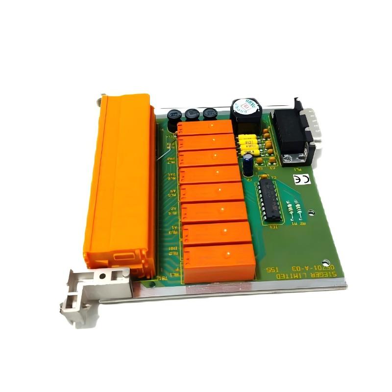
Honeywell 05701-A-0329 Control Card Function in System 57 and DCS
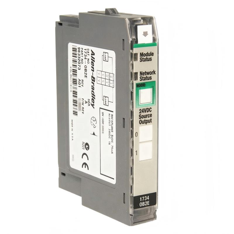
The 05701-A-0329 card is a single-channel analog or digital control card typically deployed in Honeywell Experion PKS, TDC, or System 57 racks. It handles:
- Processing one 4–20 mA analog or discrete input
- PID or ON/OFF control for a single process loop
- Alarm threshold evaluation (A1, A2, A3)
- Communication with redundant controllers
- Status indication via front-panel LEDs (Power, Fault, Inhibit)
Field Observation: In one refinery, repeated false A2 alarms were traced to a partially tilted 05701-A-0329 card. Correct seating eliminated the problem immediately.
Pre-Installation Preparation
- Shut down system power completely.
- Inspect and clean backplane connectors to remove oxidation.
- Ensure rack slots are free of mechanical damage and properly aligned.
- Verify ambient temperature is within operational limits (0–60°C).
Case Note: Oxidation on backplane connectors increased signal noise by ~10%, causing intermittent fault LED activation until cleaning was performed.
Mechanical Installation and Electrical Connection
Mechanical Procedure
- Align the card along the guide rails and insert firmly until latch engages.
- Confirm no tilt or partial seating.
- Secure the card with front-panel screws to prevent vibration loosening.
Electrical Integration
- Verify stable 24 V DC supply.
- Properly ground the card and rack chassis.
- Route analog signal cables away from high-current AC lines to prevent EMI interference.
Example: On an offshore gas platform, nearby VFDs caused unstable PID output. After rerouting cables and improving grounding, signal noise reduced from ±18 mV to ±3 mV.
Commissioning Strategy
Cold Start Verification
- Confirm Power, Fault, and Inhibit LEDs operate correctly.
- Measure baseline 4–20 mA input signal for stability.
Dynamic Testing
- Inject test signals to evaluate PID output.
- Confirm alarm threshold response timing (<1 second).
Full System Stress Test
- Activate all channels in the rack simultaneously.
- Monitor signals under thermal and mechanical stress.
- Verify no cross-channel interference.
Field Insight: Voltage drift in one offshore facility was resolved by isolating grounding paths, improving stability to ±1% deviation.