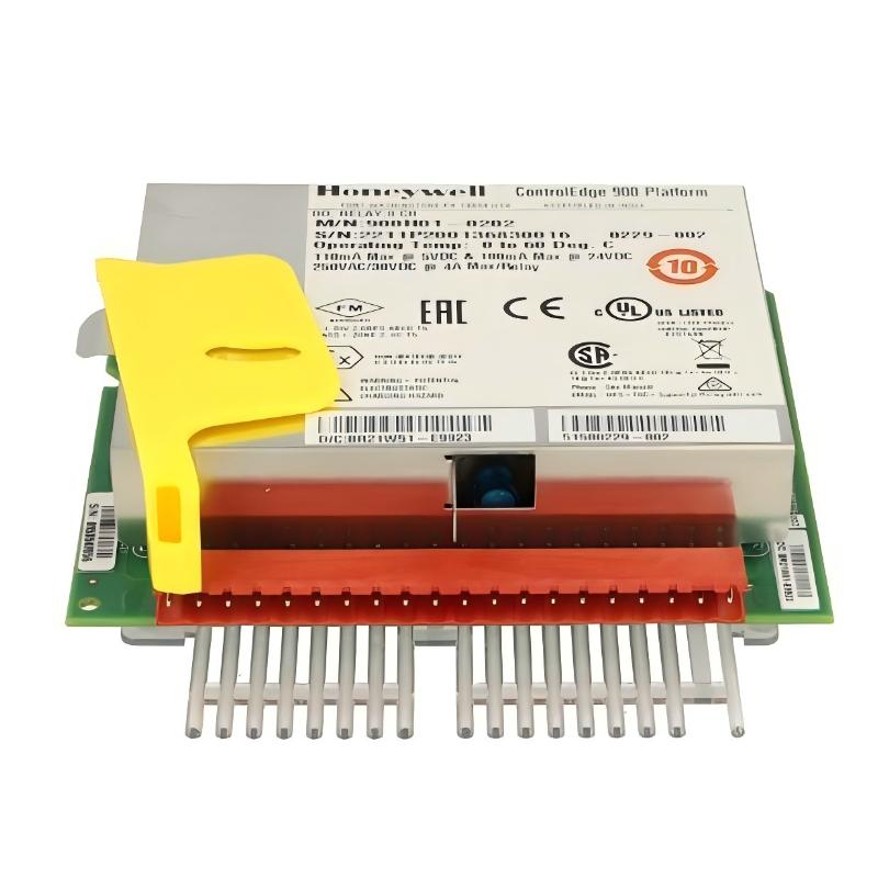
Honeywell 900H01-0202 HC900 Relay Output Module Installation & Fault Troubleshooting Guide (HC900 ControlEdge System)
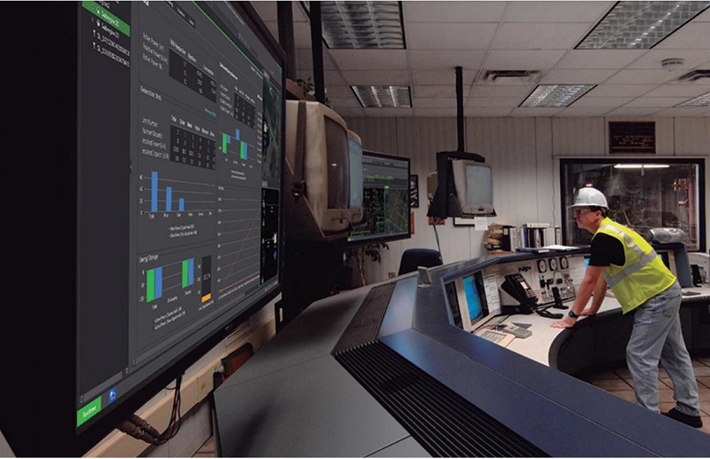
Honeywell 900H01-0202 Relay Output Module System Role in HC900 Architecture
The Honeywell 900H01-0202 relay output module is used to convert controller logic signals into physical switching actions for field devices, such as:
- Motor starters and contactors
- Solenoid valves
- Alarm horns and stack lights
- Interlock relay systems
Each module provides:
- 8 isolated relay outputs
- 4 Form A (NO) + 4 Form C (SPDT) contacts
- Independent galvanic isolation between channels
In one retrofit project at a packaging plant, this module replaced aging hardwired relay panels and reduced cabinet wiring complexity by nearly 40%.
Honeywell 900H01-0202 Installation Preparation (Field Engineering Checklist)
Before installation, engineers must validate system conditions carefully:
- Ensure stable 24V DC control supply on HC900 rack
- Verify output load type (resistive vs inductive)
- Confirm correct fuse strategy per output channel
- Check field wiring insulation resistance
- Validate terminal tightening torque on I/O base
A common field mistake is directly driving inductive loads (like contactor coils) without suppression, which significantly reduces relay lifespan.
Honeywell 900H01-0202 Wiring Strategy and Output Protection Design
Unlike transistor outputs, relay outputs are mechanical switching contacts, so wiring design must consider arc suppression:
Recommended field practice:
- For AC coils → RC snubber across load
- For DC coils → flyback diode across coil
- Always install external fuse per channel
- Avoid paralleling relay outputs unless specified
Signal flow:
HC900 Controller → 900H01 Module → Relay Contact → Field Load (motor/valve/alarm)
In one commissioning case, repeated relay welding occurred because a 7W DC contactor coil exceeded expected switching duty. After adding a suppression circuit, failure stopped completely.
Honeywell 900H01-0202 Commissioning Procedure (Field Validation Method)
After powering the system:
- Verify LED status per channel (ON/OFF response)
- Measure relay contact continuity under no-load state
- Test inductive load switching behavior under real operating conditions
- Monitor temperature rise inside cabinet during simultaneous switching
During a startup test in a water treatment facility, intermittent relay dropouts were observed. Root cause was traced to voltage dip during simultaneous valve actuation, not module failure.
Honeywell 900H01-0202 Installation Validation Checklist
A properly installed module should demonstrate:
- Stable switching under full channel activation
- No relay chatter during load switching
- Consistent ON/OFF timing (no delay drift)
- No diagnostic alarms in HC900 system scan
Field Engineering Insight
In HC900 systems:
Relay modules rarely “fail electrically” — they fail mechanically due to load stress.
Most installation issues come from:
- Missing suppression circuits on inductive loads
- Overloading relay contact ratings (especially inrush current)
- Improper grounding of control cabinets
- Thermal accumulation from high switching frequency