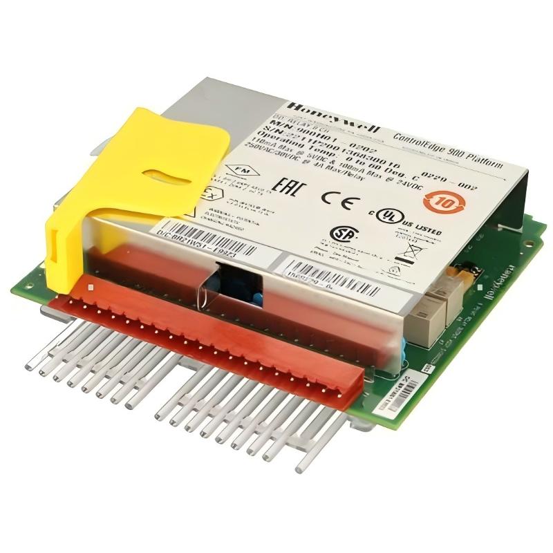
Honeywell 900H01-0202 Relay Output Module Fault Diagnosis (Output Failure Case Study in HC900 System)
Honeywell 900H01-0202 Fault Symptoms in Field Operation
Common symptoms include:
- Output LED ON but field device not responding
- Relay channel stuck ON (continuous output)
- Intermittent switching of motors or valves
- Multiple channels failing under simultaneous load
- Output works with test load but fails in real field load
In one HVAC industrial system, multiple valve failures were reported despite correct PLC logic operation.
Honeywell 900H01-0202 Fault Diagnosis Case Study (Engineering Investigation)
Initial Observation
System behavior:
- PLC output commands confirmed correct
- Channel LEDs switching normally
- Some relay outputs showed continuous voltage even when OFF
- Fault only appeared under real field load
At first glance, this looked like relay contact welding.
Engineering Root Cause Analysis
A structured test was performed:
1. No-Load Electrical Test
Relay channels toggled normally under no load conditions.
2. Field Load Isolation Test
Disconnecting field wiring restored normal switching behavior.
3. Load Measurement Analysis
Measured coil characteristics:
- DC contactor coil power ≈ 6–8W
- High inrush current at energization
4. Leakage Current Observation
Without proper suppression, residual current created partial energization paths.
Final Root Cause:
Excessive inductive load stress combined with missing suppression circuit caused relay contact degradation and apparent “sticking behavior”.
Honeywell 900H01-0202 Troubleshooting Strategy (Engineering Method)
Instead of replacing the module immediately:
Step 1: Channel-by-Channel Isolation
Test each relay output independently under controlled load.
Step 2: Load Verification
Check coil power rating and inrush current vs relay specification.
Step 3: Suppression Circuit Inspection
Verify RC snubbers or flyback diodes are installed correctly.
Step 4: Contact Integrity Test
Measure voltage drop across relay contacts under load.
Corrective Actions Applied
In this field case:
- Installed RC snubber networks across AC coils
- Added flyback diodes for DC solenoids
- Replaced one mechanically worn relay channel
- Rebalanced switching load distribution
After correction:
- All outputs returned to stable operation
- No further stuck-channel events observed
- System switching reliability restored
Honeywell 900H01-0202 Recovery Results
Post-repair performance:
- Output stability restored across all 8 channels
- Relay chatter eliminated
- No abnormal voltage leakage under OFF state
- System remained stable under continuous cycling load
Engineering Insight (Critical Lesson)
In Honeywell HC900 systems:
A “failed relay module” is often a misdiagnosed field wiring problem.
Most failures are caused by:
- Inductive load without suppression
- Overcurrent during inrush conditions
- Contact wear from frequent switching
- External wiring leakage paths
Long-Term Maintenance Recommendations
To ensure long-term reliability:
- Always match relay rating with real inrush current (not steady-state current)
- Install suppression devices on all inductive loads
- Periodically inspect terminal heating signs
- Avoid high-frequency switching near relay limit rating
- Monitor output consistency during maintenance cycles