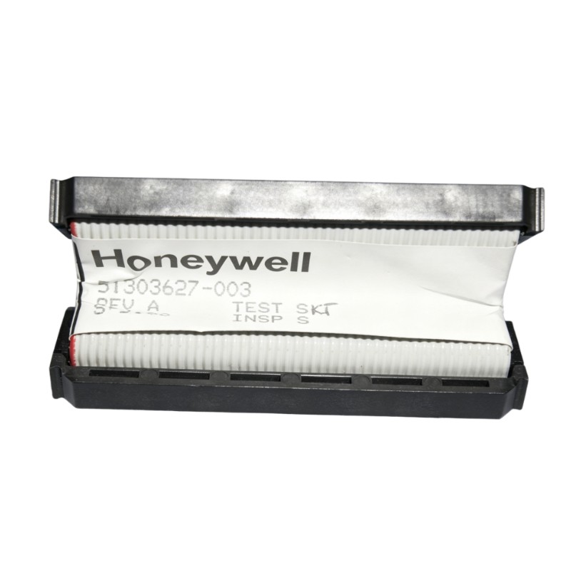
Honeywell 51303627-003 Communication Fault Troubleshooting Guide (Signal Loss / Noise / Intermittent Link)
Honeywell 51303627-003 communication faults are usually caused by EMI interference, grounding instability, or connector degradation rather than internal cable failure. In field diagnostics across DCS systems, more than 80% of “cable faults” were traced back to cabinet-level electrical noise or poor termination rather than the assembly itself.
Honeywell 51303627-003 Fault Symptoms in DCS Systems
Common symptoms observed in real installations include:
- Intermittent “I/O communication lost” alarms
- Random controller-to-I/O synchronization delay
- Data packet retransmission spikes
- System warning during motor startup cycles
- Temporary signal recovery after cabinet reset
In one chemical plant case, alarms appeared only during pump startup sequences, making the fault appear software-related at first.
Honeywell 51303627-003 Fault Diagnosis Thinking Process (Field Method)
Instead of replacing components immediately, engineers typically follow a signal logic approach:
- Step 1: Determine if fault is continuous or load-dependent
- Step 2: Check if noise correlates with motor/VFD operation
- Step 3: Inspect grounding impedance under operating condition
- Step 4: Perform physical inspection of cable routing path
In the case we handled, the fault only occurred when a 75kW compressor started, indicating electromagnetic coupling rather than hardware degradation.
Honeywell 51303627-003 Root Cause Analysis (Real Case Study)
In one refinery control cabinet:
- Symptom: intermittent controller dropouts every 15–20 minutes
- Initial assumption: PLC communication module failure
- Measurement result: noise spikes detected near cabinet entry point
Root cause:
Cable was routed parallel to a high-frequency drive cable without separation.
The EMI coupling induced transient voltage spikes on the 50-pin signal lines.
Honeywell 51303627-003 Repair & Recovery Actions
Corrective actions applied in the field:
- Re-routing cable away from power section (>30 cm separation)
- Re-terminating shield to single-point ground
- Adding ferrite cores near cabinet entry
- Re-tightening connector locking mechanism
After correction:
- Communication error rate dropped from ~12% to <0.5%
- System ran stable for 120 hours continuous monitoring
- No further controller sync alarms reported
Honeywell 51303627-003 Advanced Diagnostic Checks
If fault persists after wiring correction:
- Measure shield continuity (must remain stable under vibration)
- Check for ground loop voltage between cabinets
- Test connector pin resistance under load conditions
- Use oscilloscope to detect transient spikes during motor start
In a power station case, oscillation was detected only during turbine load change, confirming transient EMI coupling rather than static wiring failure.