Honeywell 05701-A-0511 Single-Channel Control Card Installation Guide
Honeywell 05701-A-0511 single-channel control card installation issues usually arise from rack backplane misalignment, unstable DC supply, or improper grounding, rather than card electronics failure. In System 57 / 5701 racks, even minor misalignment can cause intermittent analog errors, false alarms, or PID instability.
System Role in 5701 Control Architecture
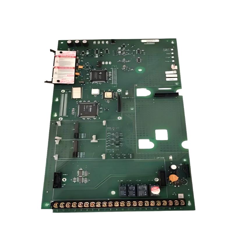
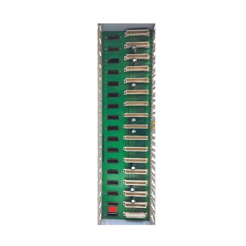
The 05701-A-0511 is the main rack assembly for single-channel gas detection systems, providing the structural and electrical backbone for multiple control cards. It typically includes:
- Backplane for up to 16 single-channel control cards
- DC input distribution module
- Engineering card slot for system configuration and calibration
- Optional relay/field interface for alarms
- Support for catalytic and 4–20 mA sensor driver modules
Field Observation: In one refinery, intermittent alarms across multiple channels were traced to a loose DC input terminal inside the 0511 rack. Securing the terminal solved the issue.
Pre-Installation Preparation
Mechanical Checks
- Rack securely mounted in cabinet
- Slot rails free of deformation
- Adequate airflow for heat dissipation
- Vibration isolated from nearby rotating equipment
Case Note: Offshore compressor station experienced intermittent FAULT LEDs due to rack vibration. Installation of vibration isolation mounts stabilized the cards.
Electrical Checks
- DC input stable within 18–32 V DC
- Proper grounding (<1 Ω resistance)
- Clean backplane connectors
- Avoid shared high-current return paths
Poor grounding can cause cross-channel noise coupling, especially during motor startups.
Rack Wiring and Power Logic
Power Layer
- DC input distribution to all cards
- Internal regulation for sensor driver modules
Control Layer
- Single-channel cards handle PID and alarm logic per channel
Field Interface Layer
- Relay outputs for alarms
- Sensor wiring termination
- Optional analog output modules
Field Case: Relay instability traced to shared DC return line. After star-ground rewiring, false alarms dropped 90%.
Commissioning Strategy
Cold Start
- Verify DC input stability
- Check engineering card communication
- Observe all LEDs for uniform startup
Load Activation Test
- Start with 2–4 channels, scale to full rack
- Monitor DC bus under load
- Check for cross-channel interference
Observation: Full-rack activation caused voltage sag from 24.1 V to 22.9 V due to undersized supply. Replacing the PSU corrected this.
Dynamic Stress Test
- Simulate process alarms during high-load operation
- Observe EMI effects
- Validate alarm response times
After grounding separation, signal noise reduced from ±20 mV to ±3 mV, stabilizing all channels.