Schneider BMXSDI1602 Discrete Input Module Installation Guide (Wiring, Configuration & M580 Commissioning)
Schneider BMXSDI1602 discrete input module installation problems are most often caused by incorrect 24V DC field wiring, channel group misassignment, or unstable sensor power supply rather than module failure. In Modicon M580 safety and standard architectures, most “input not working” cases come from wiring topology or power reference issues instead of hardware defects.
BMXSDI1602 Role in Modicon X80 Safety Architecture
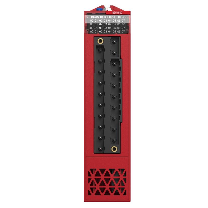
The Schneider BMXSDI1602 is a 16-channel 24V DC discrete input module used in Modicon X80 I/O systems for M580 and M340 platforms. It is designed for:
- Standard and safety-related digital input acquisition
- Field sensor status monitoring
- Emergency stop and interlock signal collection
- Industrial machine control logic input processing
In one packaging safety system, the module was used to migrate hardwired relay logic into PLC-based safety monitoring, reducing wiring complexity significantly.
Installation Preparation and Engineering Validation
Before installation, engineers focus on system-level conditions:
- Stable 24V DC power supply with load verification
- Correct grouping of input channels (two isolated 8-channel groups)
- Proper sensor type compatibility (IEC 61131-2 compliant devices)
- Verified grounding and shielding strategy
- Backplane rack condition (dust, oxidation, mechanical wear)
In one conveyor project, unstable inputs were later traced to a weak 0V reference line rather than the module itself.
Wiring and Field Installation Practice
Real commissioning work follows a strict field sequence:
- Power down the PLC rack completely before wiring
- Connect field sensors according to channel grouping (Group A / B separation)
- Ensure correct polarity for 24V DC inputs
- Maintain single-point grounding for shielded cables
- Confirm tight backplane seating of module
- Power up and observe LED channel status
In one case, swapped wiring between two channel groups caused false safety trips that looked like module failure but were purely wiring errors.
Commissioning Behavior and Validation
A correctly installed BMXSDI1602 should show:
- Stable channel LED response
- No unexpected input flickering
- Consistent PLC scan recognition
- No group-wide signal loss under load
Field example:
- Issue: random loss of multiple input channels
- Measurement: voltage drop to 13.8V during actuator switching
- Root cause: shared 24V supply with solenoid valves
- Fix: separated safety input power supply
- Result: stable 100+ hour runtime validation
Common Installation Risks
- Shared unstable 24V DC power rail
- Miswired channel grouping (A/B confusion)
- Long sensor cables without proper shielding
- Grounding loop between field devices and cabinet
- Incorrect sensor type (non-IEC compliant outputs)