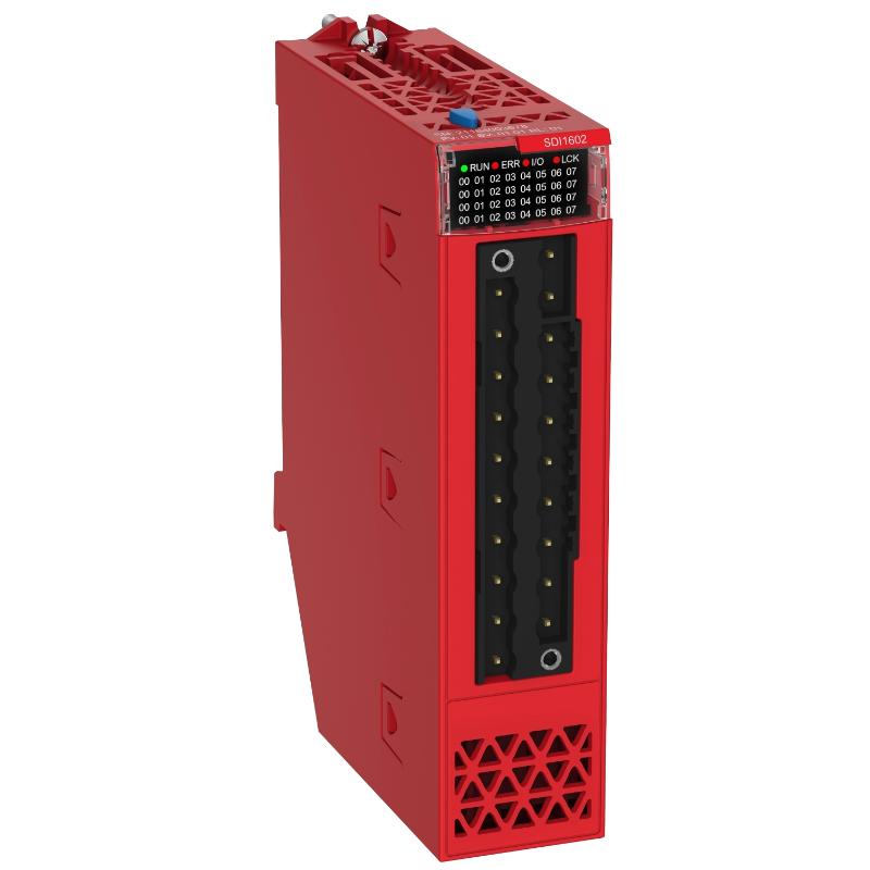
Schneider BMXSDI1602 Discrete Input Module Troubleshooting Guide (Signal Loss, Fault Diagnostics & Safety Input Failure)
Schneider BMXSDI1602 module faults are typically caused by field wiring issues, power instability, or safety configuration mismatch rather than internal module failure. In real industrial systems, especially safety-related applications, most “module faults” are actually system design or wiring issues.
Fault Symptoms in Real Industrial Applications
Common symptoms include:
- Multiple input channels not detected in PLC
- Random safety shutdown triggers
- Entire 8-channel group failure appearance
- Input signal flickering under machine load
- Diagnostic LED showing persistent fault state
In one automotive conveyor system, operators reported full safety input loss, while the module itself was fully functional.
Fault Diagnosis Method (Engineering Logic)
Instead of replacing the module directly, engineers typically follow layered diagnosis:
Power Stability Check
Measure 24V DC during actuator switching events to detect dips.
Channel Group Isolation
Compare behavior between Group A and Group B inputs.
Field Device Validation
Confirm sensors meet IEC 61131-2 voltage thresholds.
Safety Logic Review
Check PLC configuration for correct redundancy logic mapping.
In one case, incorrect safety configuration caused the system to interpret valid inputs as invalid due to mismatched logic expectations.
Real Field Case Study
Symptom: intermittent safety input dropout
Initial assumption: defective BMXSDI1602 module
Observation: dropouts occur during conveyor motor start
Measurement: 24V line drops to 13.5–14V during transient load
Root cause: shared DC supply with high inductive load circuit
Corrective actions:
- Installed dedicated 24V DC safety supply
- Separated motor and control wiring paths
- Improved grounding structure
Result: system stabilized for more than 120 hours without faults
Repair and Recovery Actions
Typical field corrections include:
- Reseating module in X80 rack backplane
- Rewiring incorrect channel group connections
- Replacing unstable power supply
- Fixing broken 0V reference line
- Adjusting safety logic configuration in PLC program
In many cases, hardware replacement is unnecessary once wiring is corrected.
Engineering Insight (EEAT Field Note)
From industrial safety automation experience:
- Most BMXSDI1602 issues are wiring or configuration related
- Voltage dips below ~14V can trigger false safety behavior
- Group-level failures often indicate power reference problems
- True module failure is rare compared to field wiring faults
Diagnosis should always follow the order:
Sensor → Wiring → Power → Configuration → Module