Allen-Bradley 1203-GU6 Enhanced DeviceNet Communication Module Installation Guide for SCANport Drive Networks
Allen-Bradley 1203-GU6 Enhanced DeviceNet communication module installation issues are typically caused by incorrect SCANport cable routing, DeviceNet node address conflicts, or unstable 24V DC supply on the communication adapter, rather than internal module failure. This module acts as a protocol bridge between SCANport drive systems and DeviceNet industrial networks, enabling full parameter access, diagnostics, and remote control.
Allen-Bradley 1203-GU6 Role in DeviceNet + SCANport Architecture
The 1203-GU6 is an Enhanced DeviceNet communication adapter designed to integrate SCANport-compatible devices into DeviceNet networks.
Core functions:
- Converts DeviceNet messages into SCANport protocol and vice versa
- Enables PLC access to drive parameters and diagnostics
- Supports single SCANport device per module
- Provides networked control for drives (e.g., PowerFlex / 1336 / 1305 series)
Field documentation confirms it acts as a gateway adapter between DeviceNet trunk and SCANport device port, using a DIN-rail mounted interface.
In one retrofit project, a 1336 drive system was successfully integrated into a modern PLC only after replacing a failed SCANport cable that caused intermittent parameter read errors.
Installation Conditions (Critical Engineering Checks)
1. Electrical Preconditions
- Stable 24V DC power supply to module
- Ripple controlled (<100 mV recommended)
- Proper grounding of DeviceNet shield at single point
- Avoid shared supply with high inductive loads
Field experience shows that voltage dips during motor start can cause DeviceNet node dropout or SCANport disconnection, even though the module remains powered.
2. DeviceNet Network Requirements
- Unique MAC ID assigned (no duplication allowed)
- Correct baud rate matching across all nodes (125k / 250k / 500k)
- Proper trunk-line termination at both ends
- CAN_H / CAN_L polarity strictly verified
A single reversed CAN line can bring down the entire DeviceNet segment.
3. SCANport Side Conditions
- SCANport cable must be shielded and properly seated (8-pin mini-DIN)
- Cable length typically <10 m for stable communication
- Avoid routing near VFD output or high-current conductors
- Ensure drive is powered before module initialization
Field note: In one packaging system, SCANport communication was unstable due to cable running parallel to inverter output cables.
Allen-Bradley 1203-GU6 Installation Procedure (Field Engineering Practice)
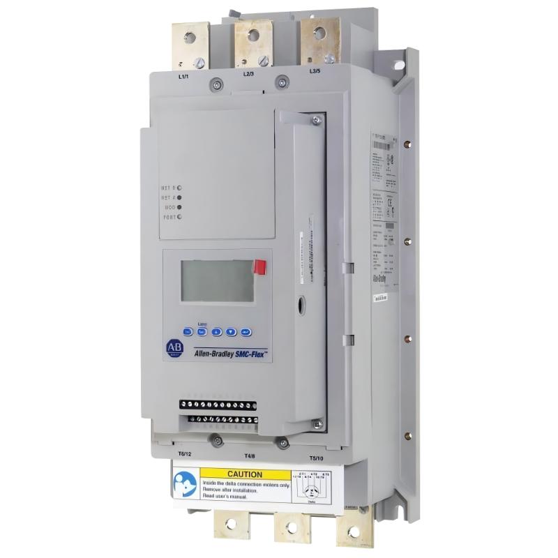
Step 1: DIN Rail Mounting
- Snap module onto 35 mm DIN rail
- Ensure full locking engagement
- Maintain airflow clearance around module
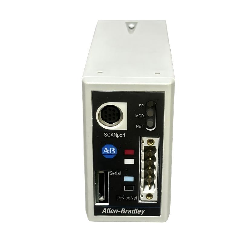
Step 2: DeviceNet Wiring
- Connect 5-pin DeviceNet connector (V+, V-, CAN_H, CAN_L, Shield)
- Verify polarity before energizing network
- Ensure correct termination resistors are installed
Step 3: SCANport Connection
- Connect SCANport cable to drive port
- Confirm secure latch engagement
- Ensure drive is powered prior to communication test
Step 4: Address Configuration
- Set unique node address (default often 63)
- Confirm no duplicate nodes during network scan
- Verify device appears in PLC scanner (RSLinx / scanner module)
Commissioning Strategy (Engineering Logic)
Step 1: Power-Up Validation
- Module LED status stable (no fault blinking)
- DeviceNet network recognized by scanner
- SCANport device detected correctly
Step 2: Parameter Access Test
- Read drive status word
- Retrieve motor speed / fault codes
- Verify parameter read/write capability
Step 3: Load Condition Test
- Start motor under light load
- Monitor communication stability during acceleration
- Check for node dropout during inrush current events
In one steel mill case, communication dropout only occurred during conveyor startup due to EMI coupling into SCANport cable routing.