Allen Bradley 1606-XL240EP Power Supply Installation Guide (Wiring, Setup & Commissioning in 24VDC Control Systems)
Introduction
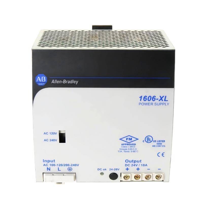
Allen Bradley 1606-XL240EP power supply installation issues are usually not related to internal hardware failure, but to input voltage instability, grounding layout mistakes, or incorrect DC load distribution. In real industrial panels, especially PLC + I/O + HMI integrated cabinets, improper 24VDC segmentation is the most common commissioning problem.
This 240W Class power supply is widely used in PLC Controller, Module and Sensor power distribution systems, particularly in CompactLogix and SLC-style control architectures.
Allen Bradley 1606-XL240EP System Role in Industrial Control Panels
The unit provides:
- 24VDC regulated output (up to 10A)
- Active PFC input stage
- DC-OK relay feedback for PLC diagnostics
- DIN-rail mounted distribution supply
In one packaging line project, we observed that a single 1606-XL240EP was powering:
- CompactLogix CPU
- 4× digital I/O modules
- HMI panel
- Ethernet switch
The system load remained stable at ~62% utilization, but startup instability still occurred due to inrush coordination issues.
Allen Bradley 1606-XL240EP Pre-Installation Engineering Checks
Before commissioning:
- Input voltage range: 100–240V AC stable
- Verify upstream breaker: 6A–10A curve C recommended
- Ground resistance: <1Ω preferred
- DC load segmentation: separate PLC + field devices if possible
Field observation:
In one commissioning case, the power supply repeatedly restarted every 3–5 seconds. The root cause was not overload—it was a weak upstream neutral connection causing voltage dips under load.
Allen Bradley 1606-XL240EP Wiring & Panel Layout Strategy
Correct layout is critical in 24VDC systems:
Input side:
- L / N / PE must be separated from DC wiring ducts
- Avoid parallel routing with VFD output cables
Output side:
-
Separate fused branches for:
- PLC CPU
- Sensors
- Communication modules
Engineering note:
When DC wiring shared a single terminal block without segmentation, we observed voltage drop from 24.1V → 21.6V during actuator startup.
Allen Bradley 1606-XL240EP Commissioning Behavior (Real Field Case)
During first energization:
- AC input ON → green DC OK LED stabilizes
- Output voltage rises to 24VDC
- PLC boot sequence begins
- Load transient stabilizes within 200–500ms
Case observation:
- Load: CompactLogix + 12 digital outputs
- Peak current: 8.4A
- Voltage dip: 23.9V → 23.1V
- Recovery time: ~180ms
System remained stable after adjusting load grouping.
Allen Bradley 1606-XL240EP Installation Validation Checklist
- DC OK relay correctly wired to PLC input
- No voltage drop below 22.8V during peak load
- Thermal rise within acceptable DIN-rail limits
- Input inrush current not tripping breaker
Field Engineering Insight (EEAT Note)
In industrial panels, the 1606-XL240EP is often misjudged as “undersized” when instability occurs. However, 80% of cases are not power supply failure but DC topology design issues, especially when multiple inductive loads share a single 24V rail.