Schneider 140CPS214000 Power Supply Installation Guide (Wiring, Configuration & Quantum Rack Commissioning)
Introduction
Schneider 140CPS214000 installation issues are often misdiagnosed as module failure, but in field systems the real causes are usually incorrect DC supply design, improper fusing, or excessive backplane load during expansion.
Unlike small DIN-rail PSUs, this module powers an entire Quantum backplane, so even minor wiring issues can propagate as CPU or I/O faults.
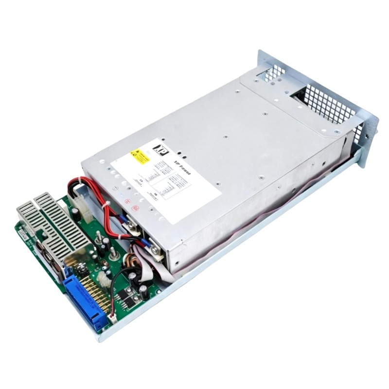
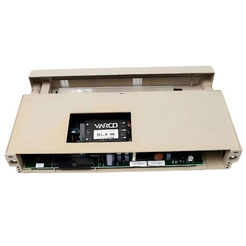
Schneider 140CPS214000 Role in Quantum Architecture
The module provides:
- 24V DC input conversion (20–30 V DC range)
- 5.1V backplane power generation
- Up to ~8A distributed rack current
- Power fault relay output
- Internal overload and overvoltage protection
In one wastewater treatment control rack, a single 140CPS214000 was powering:
- CPU module
- 6 digital I/O modules
- 2 analog input modules
- Ethernet communication module
System initially appeared unstable during expansion, but PSU was not defective—the rack load distribution exceeded safe transient limits.
Schneider 140CPS214000 Pre-Installation Engineering Checks
Before commissioning:
- Verify DC input stability (20–30V DC range)
- Ensure correct polarity (reverse polarity blocks startup)
- Confirm external fuse (typically slow-blow 5A recommended)
- Check backplane load calculation before adding I/O modules
- Ensure grounding is bonded to rack chassis
Field observation:
One Quantum rack failed to start intermittently because DC input dipped below 18V during solenoid switching events in the same cabinet.
Wiring & Rack Integration Strategy
Unlike DIN-rail systems, this module depends heavily on backplane stability.
Input side:
- Use short, low-resistance DC wiring
- Avoid sharing supply with high inrush inductive loads
- Install dedicated DC protection fuse
Rack side:
- Avoid sudden I/O expansion without recalculating power budget
- Maintain proper module seating force on backplane connectors
Engineering insight:
When an analog module was added without recalculating load, the system experienced intermittent CPU reset during peak scan cycles, even though PSU output voltage remained “normal”.
Schneider 140CPS214000 Commissioning Behavior (Field Example)
Startup sequence:
- DC input applied (24V nominal)
- PSU initializes internal DC/DC conversion
- Backplane 5.1V rail stabilizes
- CPU begins execution cycle
- I/O modules enter scan state
Real case:
- System: Quantum PLC controlling batching process
- Load: CPU + 8 I/O modules
- Symptom: random “rack power fault” during startup
- Observation: DC input dropped to ~19.6V during peak load
After separating DC supply from solenoid circuit:
- Startup stabilized
- No further rack fault events
Installation Validation Checklist
- Backplane voltage stable under full module load
- No “power fault” relay activation
- Stable CPU boot without reset
- DC input remains above minimum threshold under load
- No intermittent I/O drop during scan cycle
Field Engineering Insight
In Quantum systems, the 140CPS214000 is often blamed for rack instability. However, in most field cases, instability originates from DC bus disturbance caused by external loads sharing the same supply rail, not the PSU itself.