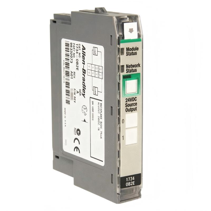
Allen-Bradley 1734-OB2E Point I/O 2 Point Digital Output Module Installation Guide (Wiring & Commissioning)
Allen-Bradley 1734-OB2E Point I/O digital output module installation problems are usually related to field wiring, 24V DC power distribution, or incorrect I/O configuration rather than a defective output module. During commissioning of distributed control systems, engineers often find that the PLC recognizes the module correctly, but field devices fail to energize because output addressing, terminal base wiring, or load protection has not been verified.
The Allen-Bradley 1734-OB2E Point I/O 2 Point Digital Output Module is a 24V DC, 2-channel source output module with electronic protection functions designed for distributed automation applications. It supports point-level diagnostics and is commonly used for controlling solenoid valves, contactors, relays, and small actuators.
Allen-Bradley 1734-OB2E Point I/O Module Installation Overview and Control Application
The 1734-OB2E is typically installed in an Allen-Bradley POINT I/O system connected through communication adapters such as EtherNet/IP or other fieldbus interfaces.
Typical applications include:
- Pneumatic valve control
- Motor starter enable signals
- Conveyor actuator commands
- Machine interlock outputs
In one packaging machine commissioning case, a 1734-OB2E module controlled two pneumatic cylinders.
Initial startup condition:
- PLC communication: Normal
- Module status LED: Healthy
- Output command from PLC: ON
- Cylinder movement: No response
The first assumption was a damaged output channel. However, field measurement showed:
- Output command: 24V DC available in PLC logic
- Terminal voltage: 0V at actuator side
The investigation identified a reversed common wiring connection at the terminal base.
After correction, both output channels operated normally.
Allen-Bradley 1734-OB2E Installation Preparation and Hardware Configuration Check
Before mounting the Point I/O output module, verify:
- POINTBus power availability
- Terminal base installation condition
- 24V DC field supply stability
- Output load current requirement
- Network adapter configuration
The 1734-OB2E provides:
- Two digital output channels
- 24V DC sourcing output
- Electronic protection
- Operating temperature range of approximately -20…55 °C
A field engineer should confirm the load characteristics before energizing.
Example:
Solenoid valve specification:
- Coil voltage: 24V DC
- Coil current: 0.35A
Module capability:
- Output channel capacity: suitable for typical 24V DC actuator loads
Allen-Bradley 1734-OB2E Wiring Installation and Field Device Connection
Correct wiring is critical because digital output faults often originate from external circuits.
Recommended wiring checks:
- Confirm output channel assignment
- Verify actuator positive terminal connection
- Check DC common reference
- Separate output wiring from high-current cables
Typical wiring logic:
PLC Output Command
        |
1734-OB2E Channel 0
        |
24V DC Field Device
        |
0V DC Return
In one water treatment system:
Observed issue:
- Channel 0 worked correctly
- Channel 1 showed overload indication
Measured values:
Before correction:
- Load current: 1.35A
- Rated channel current exceeded
Root cause:
A valve coil had been replaced with an incorrect higher-power model.
After replacement:
- Current reduced to 0.42A
- Output diagnostic cleared automatically
Allen-Bradley 1734-OB2E Studio 5000 Setup and I/O Configuration
The software configuration stage requires matching the physical hardware with the controller project.
Important configuration items:
- Correct module selection
- Network address assignment
- Input/output tag mapping
- Module fault handling logic
Typical PLC logic:
IF Machine_Enable = TRUE
AND Safety_OK = TRUE
THEN
1734_OB2E_Output_0 = ON
During commissioning, engineers should monitor:
- Command status
- Output feedback
- Module diagnostic bits
A common mistake is testing output forcing without checking whether the safety or interlock logic is preventing activation.
Allen-Bradley 1734-OB2E Commissioning Validation and System Testing
A proper commissioning process should include:
Electrical Validation
Check:
- 24V DC voltage at module terminals
- Output voltage under load
- Current consumption
Functional Validation
Test:
- Individual output channels
- Machine sequence response
- Fault recovery behavior
Real commissioning data:
Before adjustment:
- Output response delay: 450 ms
- Intermittent actuator dropout observed
After correcting DC power distribution:
- Output voltage stabilized at 24.1V DC
- Response delay reduced below 100 ms
The 1734-OB2E installation process is successful only when PLC logic, module diagnostics, and field devices operate together.