Allen-Bradley 1336-BDB-SP76D Gate Driver Installation Guide (Setup & Commissioning)
Allen-Bradley 1336-BDB-SP76D Gate Driver installation problems are usually caused by incomplete power section inspection, incorrect replacement procedures, or hidden inverter faults rather than the gate driver board itself. In high-power AC drive systems, the gate driver is directly responsible for controlling the switching devices, so incorrect installation can lead to repeated overcurrent trips, startup failures, or immediate component damage.
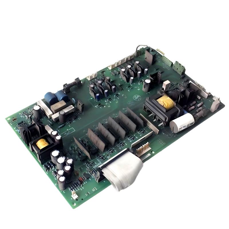
The Allen-Bradley 1336-BDB-SP76D Gate Driver is a critical power control component used in 1336 series AC drive systems. It provides switching control signals between the drive control electronics and the inverter power stage, allowing the power transistors to operate correctly during motor acceleration and running conditions.
Allen-Bradley 1336-BDB-SP76D Gate Driver Application Overview
The gate driver works as the control interface between the low-voltage control system and the high-power switching section.
Typical drive structure:
Drive Control Board
        |
        |
1336-BDB-SP76D Gate Driver
        |
        |
Power Switching Module
        |
        |
Motor Output
The main functions include:
- Generating switching signals
- Controlling inverter timing
- Providing isolation between control and power circuits
- Protecting switching devices during abnormal operation
Typical industrial applications:
- Large motor drives
- Conveyor systems
- Pumps and compressors
- Heavy manufacturing equipment
- High-power automation systems
In one steel production facility, a 1336 drive experienced repeated shutdowns during motor acceleration after years of operation.
Initial observations:
- Operator interface worked normally
- Drive parameters could be accessed
- Motor failed during acceleration
- Overcurrent faults appeared randomly
The maintenance team first suspected motor problems.
During field inspection, engineers analyzed the inverter section and found unstable switching behavior from the gate control circuit.
After replacing the 1336-BDB-SP76D gate driver and checking the surrounding power components:
- Motor acceleration returned to normal
- Output current became balanced
- Drive operated continuously under production load
The failure was related to gate control stability, not the motor.
Allen-Bradley 1336-BDB-SP76D Installation Preparation and Safety Inspection
Before installing the gate driver, engineers must inspect the complete drive system.
Required preparation:
- Disconnect incoming power supply
- Verify DC bus discharge
- Inspect power switching components
- Check cooling system condition
- Confirm replacement board compatibility
Installation checklist:
| Inspection Item | Engineering Requirement |
|---|---|
| Main power | Completely isolated |
| DC bus voltage | Confirm safe level |
| Board connectors | Correct connection |
| Power module | No short circuit damage |
| Cooling airflow | Clean and sufficient |
A common field mistake is replacing the gate driver immediately after an overcurrent fault without checking the inverter power stage.
If the power switching device has failed, the replacement gate driver may fail again during startup.
Allen-Bradley 1336-BDB-SP76D Gate Driver Board Installation Process
The installation requires careful handling because the board controls high-energy switching circuits.
Recommended procedure:
- Remove the damaged gate driver board
- Inspect connectors for overheating
- Check wiring condition
- Install replacement board
- Verify mechanical fixing
- Confirm electrical connections
During one maintenance repair:
Before replacement:
- Startup success rate: 30%
- DC bus voltage: Normal
- Output current: Unstable
Inspection findings:
- Gate signal connection showed contact degradation
- Power section had no short circuit
- Cooling system operated correctly
After installation:
- Startup became stable
- Motor current balance improved
- Drive passed full-load testing
The key point was not only replacing the board but confirming the entire inverter condition.
Allen-Bradley 1336-BDB-SP76D Drive Setup and Commissioning Strategy
After installation, commissioning should be performed gradually.
Recommended sequence:
Power Section Verification
Check:
- DC bus charging condition
- No abnormal current increase
- No immediate protection fault
Motor Operation Test
Verify:
- Rotation direction
- Acceleration response
- Output current stability
Typical commissioning logic:
IF DC_Bus_Status = Normal
AND Gate_Control = Stable
AND Output_Current = Balanced

THEN

Enable Motor Operation
During commissioning, engineers should monitor:
- Output current
- Drive temperature
- Fault history
- Acceleration performance
A drive that starts without load may still fail when torque demand increases.
Allen-Bradley 1336-BDB-SP76D Commissioning Validation and Performance Testing
Final testing should confirm both electrical and mechanical performance.
Example field results:
Before repair:
- Startup failure: 5 times/day
- Current imbalance: 16%
- Acceleration unstable
After repair:
- Startup failure: 0
- Current imbalance: below 3%
- Continuous operation: 72 hours stable
A successful 1336-BDB-SP76D installation requires correct replacement, inverter inspection, and complete drive validation.