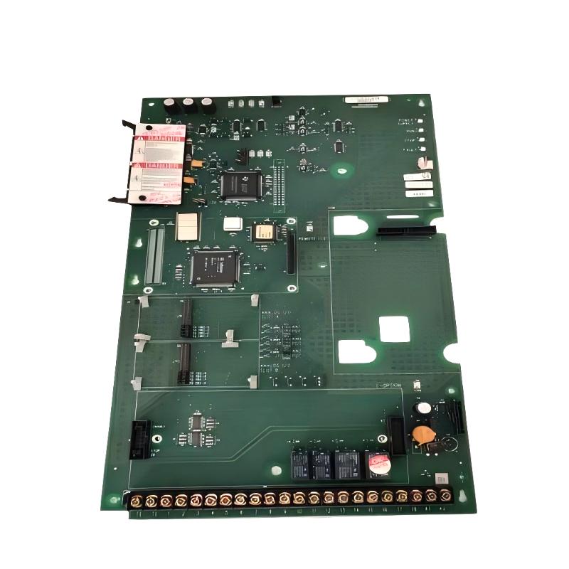
Allen-Bradley 1336F-MCB-SP1F Drive Control Board Installation Guide (Setup & Commissioning)
Allen-Bradley 1336F-MCB-SP1F Drive Control Board installation problems are usually caused by incorrect replacement procedures, poor connector inspection, or incomplete drive configuration checks rather than a defective control board itself. In industrial variable frequency drive systems, the control board manages communication between operator commands, control signals, and inverter operation, so incorrect installation can lead to startup failure, missing I/O signals, or unstable drive behavior.
The Allen-Bradley 1336F-MCB-SP1F Drive Control Board is the main control circuit board used in 1336 Plus II drive systems. It manages drive control functions, external I/O interfaces, communication connections, and coordination between the control section and power section.
Allen-Bradley 1336F-MCB-SP1F Drive Control Board Application Overview
The control board acts as the central processing unit of the variable frequency drive.
Typical drive structure:
PLC / Operator Command
          |
          |
1336F-MCB-SP1F Control Board
          |
          |
Drive Control Interface
          |
          |
Power Section
          |
          |
Motor
Main functions include:
- Processing start/stop commands
- Managing analog and digital signals
- Controlling drive operating logic
- Communicating with external devices
- Coordinating inverter operation
Typical applications:
- Industrial motor control systems
- Production line equipment
- Pumps and fans
- Conveyor applications
- Machine automation systems
In one manufacturing plant, a 1336 Plus II drive suddenly stopped responding to external start commands.
Initial observations:
- Display module powered normally
- Drive had incoming power
- Motor and power section showed no obvious damage
- PLC output signal was present
The maintenance team initially suspected a PLC communication problem.
Engineers performed a control system analysis:
- Checked PLC output voltage
- Verified terminal wiring
- Tested control board input response
- Reviewed fault history
Measured condition:
Before repair:
- PLC output signal: 24V DC normal
- Drive input response: intermittent
- Control command recognition: unstable
After replacing and correctly installing the 1336F-MCB-SP1F Drive Control Board:
- Start command response became stable
- External I/O operation recovered
- Drive completed production testing
The failure was caused by control board signal processing instability.
Allen-Bradley 1336F-MCB-SP1F Installation Preparation and Safety Inspection
Before replacing the drive control board, engineers must prepare the drive correctly.
Required preparation:
- Disconnect incoming power
- Verify DC bus discharge
- Record existing parameters
- Label all connectors
- Inspect surrounding components
Installation checklist:
| Inspection Item | Engineering Requirement |
|---|---|
| Power supply | Fully disconnected |
| DC bus voltage | Confirm safe level |
| Connectors | Correct identification |
| Parameters | Backup completed |
| Wiring | No damage or looseness |
A common field mistake is removing the control board immediately after a drive fault without documenting the original configuration.
Important information to record:
- Drive parameters
- Communication settings
- Input/output assignments
- Fault history
This prevents configuration loss after replacement.
Allen-Bradley 1336F-MCB-SP1F Drive Control Board Replacement Procedure
The installation process requires careful handling because the board contains sensitive electronic circuits.
Recommended replacement procedure:
- Remove drive power completely
- Confirm capacitor discharge
- Disconnect communication cables
- Remove existing control board
- Inspect mounting points
- Install replacement board
- Reconnect all terminals
Before startup, engineers should verify:
- Control connectors
- Terminal wiring
- Ground connections
- Communication interfaces
In one field replacement case:
Before installation:
- Drive communication failure: intermittent
- Digital input response delay: 2–3 seconds
- Motor control: unavailable
Inspection found:
- Control board connector oxidation
- Poor signal contact condition
After replacement:
- Input response time returned normal
- Communication became stable
- Machine restarted successfully
Allen-Bradley 1336F-MCB-SP1F Drive Setup and System Configuration
After hardware installation, commissioning requires configuration verification.
Important setup areas:
- Input signal assignment
- Output configuration
- Communication settings
- Drive parameters
- Control source selection
Typical commissioning logic:
IF Control_Board_Status = Normal
AND Input_Signal = Valid
AND Parameter_Setup = Correct

THEN

Enable Drive Operation
Engineers should confirm:
- Local control operation
- Remote control operation
- PLC command response
- Fault reset function
A control board replacement without configuration verification may create new operational problems.
Allen-Bradley 1336F-MCB-SP1F Commissioning Validation and Performance Testing
Final commissioning should include complete functional testing.
Testing procedure:
Control Signal Test
Verify:
- Start command
- Stop command
- Speed reference
- Fault reset
Drive Operation Test
Check:
- Motor startup
- Acceleration response
- Running stability
Example field validation:
Before repair:
- Start command failure rate: 30%
- Communication interruption: frequent
- Production stops: 4 times/day
After repair:
- Start command response: stable
- Communication: continuous
- Production test: 72 hours without interruption
A successful Allen-Bradley 1336F-MCB-SP1F installation requires correct replacement, parameter verification, and complete system commissioning.