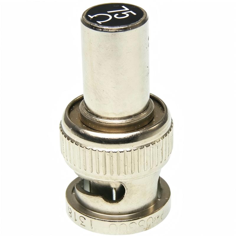
Allen-Bradley 1786-XT ControlNet 75 Ohm Terminator Plug Installation Guide (Network Setup & Commissioning)
Allen-Bradley 1786-XT ControlNet 75 Ohm Terminator Plug installation problems are usually caused by incorrect termination location, missing end-of-line termination, or poor coaxial cable connection rather than a failure of PLC communication modules. In industrial ControlNet networks, the 1786-XT is a small but critical component. Incorrect installation can cause intermittent communication faults, node dropouts, unstable remote I/O updates, and difficult-to-trace network errors.
The Allen-Bradley 1786-XT ControlNet 75 Ohm Terminator Plug is a passive network termination device designed for ControlNet coaxial communication systems. It provides the required impedance matching at the physical ends of a ControlNet segment, helping maintain signal quality and reliable data transmission.
Allen-Bradley 1786-XT ControlNet Terminator Plug Application Overview
The 1786-XT is used in ControlNet network physical-layer design to prevent signal reflection and maintain stable communication performance.
Typical ControlNet network structure:
ControlNet PLC Controller
          |
          |
ControlNet Coaxial Cable
          |
          |
Remote Communication Nodes
          |
          |
1786-XT 75Ω Terminator
The main functions include:
- Maintaining ControlNet network impedance
- Reducing signal reflection
- Improving communication stability
- Supporting reliable remote I/O data exchange
- Improving long-distance network performance
Typical applications:
- ControlLogix ControlNet systems
- Distributed Flex I/O networks
- Factory automation systems
- Process control systems
- Large industrial communication networks
In one manufacturing facility, engineers expanded an existing ControlNet network by adding a new remote I/O cabinet.
After installation:
- PLC processor status: Normal
- Communication module status: Normal
- Remote I/O communication: Intermittent
The maintenance team initially suspected a damaged communication module.
The engineering team performed a field investigation:
- Checked ControlNet cable routing
- Verified network topology
- Inspected termination points
- Tested communication stability
Inspection results:
Before correction:
- ControlNet nodes online: Normal
- Communication errors: Increasing
- Remote I/O update: Delayed
The investigation found that the physical end of the ControlNet segment did not have the correct termination.
After installing the 1786-XT correctly:
- Communication alarms disappeared
- Remote I/O response became stable
- Network operation returned to normal
The problem was caused by network termination, not hardware failure.
Allen-Bradley 1786-XT Installation Preparation and ControlNet Network Planning
Before installing the ControlNet terminator plug, engineers must understand the complete network structure.
Preparation requirements:
- Identify the beginning and end of the ControlNet segment
- Confirm coaxial cable layout
- Verify existing terminator locations
- Check connector condition
- Record network topology
Installation checklist:
| Inspection Item | Engineering Requirement |
|---|---|
| Network cable | Correct ControlNet coaxial cable |
| Termination position | Physical end of segment |
| Resistance | 75 ohm matching |
| Connector | Secure BNC connection |
| Network design | Correct topology |
A common field mistake is installing terminators based on cabinet location instead of the actual electrical end of the network segment.
ControlNet termination rules:
- One terminator at each physical end
- No additional terminators in the middle
- Correct impedance must be maintained
Allen-Bradley 1786-XT ControlNet Terminator Plug Installation Process
Although the 1786-XT installation is simple, the installation position determines network performance.
Recommended installation procedure:
- Power down the ControlNet system if required by maintenance procedure
- Locate the final ControlNet tap
- Inspect BNC connector condition
- Install the 1786-XT terminator
- Confirm mechanical connection
- Restart communication system
After installation, engineers should verify:
- Network node status
- Communication stability
- Remote I/O response
- Network diagnostic information
In one commissioning case:
Initial condition:
- ControlNet communication active
- Network errors appearing randomly
- Remote devices occasionally unavailable
Investigation found:
- One end of the network cable was left unterminated
- Signal quality decreased during operation
After correction:
- Network communication became stable
- Error counters stopped increasing
- Production equipment operated normally
Allen-Bradley 1786-XT ControlNet Network Setup and Signal Validation
After physical installation, engineers should perform communication validation.
Important checks:
- ControlNet node availability
- Network error status
- Communication response time
- Remote I/O update performance
Typical commissioning logic:
IF Network_Topology = Correct
AND Terminators = Installed
AND Cable_Connection = Reliable

THEN

Enable Stable ControlNet Communication
Engineers should verify:
- All nodes remain online
- PLC data exchange is continuous
- No communication retry events occur
- Remote devices respond correctly
Field experience shows that many ControlNet faults are caused by physical-layer problems rather than PLC programming issues.
Allen-Bradley 1786-XT Commissioning Validation and Performance Testing
Final commissioning should confirm long-term network reliability.
ControlNet Communication Test
Verify:
- Node stability
- Network error counters
- Communication response
Physical Inspection
Check:
- Terminator installation
- Cable condition
- Connector tightness
Example field validation:
Before correction:
- Communication faults: 8 times/day
- Remote I/O delay: 2–4 seconds
- Production alarms: Frequent
After correction:
- Communication faults: 0
- Network response: Stable
- 7-day continuous operation completed
A successful Allen-Bradley 1786-XT installation requires correct termination, proper ControlNet network design, and complete commissioning verification.