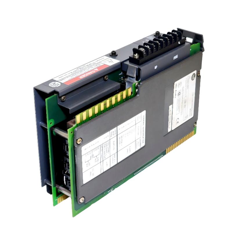
Allen-Bradley 1402-LS51 Line Synchronization Module Troubleshooting Guide (Fault Diagnosis)
Allen-Bradley 1402-LS51 Line Synchronization Module faults are commonly caused by incorrect voltage measurement, phase sequence errors, frequency mismatch, or PLC configuration problems rather than internal module damage. In industrial synchronization systems, replacing the module without checking the electrical measurement chain often fails to solve the real problem.
This article explains a field troubleshooting case where a generator synchronization system could not complete automatic connection.
Allen-Bradley 1402-LS51 Line Synchronization Module Fault Symptoms
Typical fault symptoms include:
- Generator breaker cannot close
- Synchronization permission unavailable
- Phase angle value abnormal
- Frequency matching takes too long
- PLC receives incorrect synchronization status
Field case:
A factory backup generator system failed during automatic transfer testing.
Initial observations:
- Generator engine started normally
- PLC program executed correctly
- Synchronization process stopped before breaker closing
The maintenance team suspected:
- Synchronization module failure
- PLC logic problem
- Generator controller issue
Engineers started diagnosis from the measurement system.
Allen-Bradley 1402-LS51 Fault Diagnosis Process and Measurement Analysis
Troubleshooting path:
Generator System
        |
        |
Voltage Measurement Circuit
        |
        |
1402-LS51 Synchronization Module
        |
        |
PLC Controller
        |
        |
Breaker Control
Engineers checked:
- Voltage measurement values
- Frequency difference
- Phase angle information
- PLC received data
Diagnostic results:
- PLC operation: Normal
- Module communication: Normal
- Synchronization calculation: Abnormal
The fault was isolated to the electrical measurement input.
Allen-Bradley 1402-LS51 Phase Measurement Fault Investigation
Field measurements:
Before repair:
- Bus voltage: 415 VAC
- Generator voltage: 414 VAC
- Frequency difference: 0.15 Hz
- Phase angle reading: Incorrect
The engineering team compared:
- Actual electrical waveform
- Module measurement data
- Wiring drawings
The investigation found:
- One voltage sensing channel had incorrect phase wiring
Technical impact:
Incorrect phase input caused:
- Wrong phase angle calculation
- Synchronization window rejection
- Breaker close command blocked
The 1402-LS51 module itself was operating normally.
Allen-Bradley 1402-LS51 Root Cause Analysis and Recovery
The final root cause was incorrect field wiring after maintenance work.
Original condition:
- Generator synchronization worked normally
- Voltage sensing wiring was correct
After maintenance:
- Measurement wires were reconnected incorrectly
- Phase relationship changed
Failure pattern:
Normal condition:
- Accurate voltage and phase measurement
Fault condition:
- Incorrect synchronization calculation
- Generator unable to connect to power bus
Engineering conclusion:
The failure was caused by electrical measurement error, not hardware failure.
Allen-Bradley 1402-LS51 Troubleshooting Repair and System Recovery
Corrective actions:
Electrical Input Correction
Performed:
- Reconnected voltage sensing wires
- Verified phase sequence
- Confirmed measurement accuracy
Synchronization System Testing
Tested:
- Generator startup
- Voltage matching
- Frequency matching
- Breaker operation
Final results:
Before repair:
- Synchronization failed repeatedly
- Generator unavailable for automatic transfer
After repair:
- Synchronization completed normally
- Automatic transfer test passed
- System returned to standby operation
Allen-Bradley 1402-LS51 Common Fault Patterns and Diagnostic Methods
Phase Sequence Fault
Symptoms:
- Phase angle abnormal
- Synchronization never completes
Diagnosis:
- Check three-phase sequence
- Verify voltage input wiring
Frequency Matching Fault
Symptoms:
- Synchronization process takes too long
- Generator speed adjustment continues
Diagnosis:
- Check governor control
- Verify frequency measurement accuracy
PLC Configuration Fault
Symptoms:
- Module data appears incorrect
- Synchronization logic does not respond
Diagnosis:
- Review PLC configuration
- Check module data mapping
- Verify communication status
Allen-Bradley 1402-LS51 Long-Term Maintenance Strategy
For reliable synchronization operation:
- Maintain updated electrical drawings
- Record synchronization parameters
- Inspect voltage sensing wiring regularly
- Monitor abnormal measurement trends
- Backup PLC configuration data
A practical engineering rule:
“When an Allen-Bradley 1402-LS51 synchronization fault occurs, verify measurement accuracy and phase relationship before replacing the module.”
Recommended troubleshooting sequence:
Electrical input inspection → Voltage verification → Phase sequence check → PLC data analysis → Synchronization testing → Final system validation.