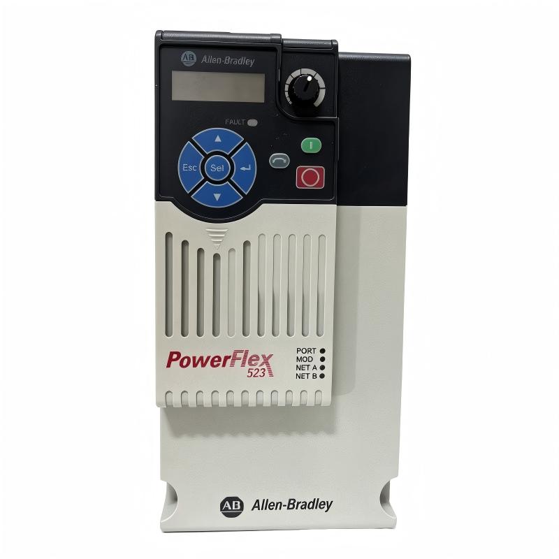
Allen-Bradley 25A-D017N114 PowerFlex 523 AC Drive Installation Guide (Wiring & Commissioning)
Allen-Bradley 25A-D017N114 PowerFlex 523 AC Drive installation problems are usually caused by incorrect motor parameter settings, improper wiring, unsuitable acceleration configuration, or incorrect control mode selection rather than drive hardware failure. In industrial automation projects, a newly installed AC drive may power up correctly but still fail to provide stable motor operation because the commissioning parameters do not match the actual machine load.
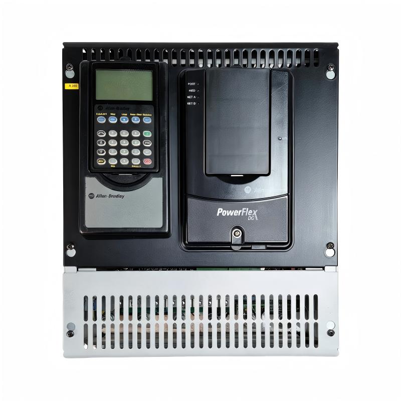
The Allen-Bradley 25A-D017N114 PowerFlex 523 AC Drive is a compact variable frequency drive designed for general industrial motor control applications. It provides adjustable speed control, motor protection, and flexible machine integration for conveyors, pumps, fans, and automation equipment.
Allen-Bradley 25A-D017N114 PowerFlex 523 AC Drive Application Overview
The PowerFlex 523 AC Drive regulates motor speed by controlling output frequency and voltage, allowing machines to operate according to production requirements.
Typical control structure:
Three Phase AC Power
          |
          |
Allen-Bradley 25A-D017N114 PowerFlex 523 Drive
          |
          |
Three Phase Motor
          |
          |
Industrial Machine Load
Common applications:
- Conveyor systems
- Packaging equipment
- Material handling machines
- Industrial fans
- Small process pumps
Main functions:
- Variable speed control
- Motor overload protection
- Adjustable acceleration and deceleration
- Machine automation integration
- Energy-efficient motor operation
The drive is often selected for applications where compact installation and reliable motor control are required.
Allen-Bradley 25A-D017N114 Installation Preparation and Engineering Inspection
Before installing the PowerFlex 523 drive, engineers should evaluate the complete motor control system instead of only checking motor horsepower.
Important preparation items:
| Inspection Area | Engineering Check |
|---|---|
| Motor rating | Confirm voltage and current |
| Power supply | Verify compatible input voltage |
| Motor cable | Select correct cable size |
| Grounding | Ensure reliable grounding |
| Control system | Confirm PLC or terminal control |
Field experience shows that many startup problems are caused by incomplete preparation.
For example:
A machine builder installed a PowerFlex 523 drive on a conveyor system. The electrical installation was completed correctly, but the motor parameters were copied from another machine.
During commissioning:
- Drive status: Normal
- Motor rotation: Normal
- Speed control: Unstable
After checking the motor nameplate, engineers found that rated current values were different.
After entering the correct motor data:
- Motor current decreased
- Speed response improved
- Conveyor operation became stable
The issue was configuration accuracy, not drive quality.
Allen-Bradley 25A-D017N114 PowerFlex 523 Wiring Installation
Correct wiring is essential for stable AC drive operation.
Power Connection Inspection
Engineers should verify:
- Three-phase input terminals
- Protective circuit connection
- Ground terminal
- Cable tightening condition
Loose power connections may cause:
- Voltage fluctuation
- Unexpected trips
- Excessive heating
Motor Output Wiring Check
Confirm:
- Motor U/V/W terminals
- Motor grounding
- Cable insulation condition
Incorrect motor wiring can result in:
- Wrong rotation direction
- Overcurrent alarms
- Motor startup failure
Control Wiring Verification
Check:
- Start signal
- Stop signal
- Analog speed reference
- Communication interface
During one commissioning project, the drive displayed normal operation but the motor stopped immediately after startup.
The engineering team measured:
- Input voltage: 460 VAC
- Control signal: Normal
- Output command: Active
Further inspection found that the start/stop control mode was incorrectly configured.
After correcting the control source:
- Motor started normally
- PLC control was restored
Allen-Bradley 25A-D017N114 Setup and System Configuration
The setup process determines the final performance of the PowerFlex 523 AC Drive.
Important parameters include:
- Motor voltage
- Motor current
- Motor frequency
- Maximum frequency
- Minimum frequency
- Acceleration time
- Deceleration time
- Control source
Typical commissioning logic:
IF Motor_Data = Correct
AND Wiring_Status = Normal
AND Control_Mode = Correct

THEN

Enable Motor Operation
Engineers should verify:
- Motor direction
- Running current
- Speed response
- Protection functions
A frequent field mistake is operating the drive with factory default parameters.
Incorrect settings may cause:
- Slow acceleration
- Motor overheating
- Overcurrent trips
- Poor speed regulation
Allen-Bradley 25A-D017N114 Commissioning Testing and Performance Validation
Final commissioning should include actual machine operation testing.
Motor Running Test
Check:
- Startup response
- Speed adjustment
- Current stability
- Stop performance
Load Test
Verify:
- Mechanical movement
- Production speed
- Motor temperature
- Long-term stability
One field commissioning result:
Before optimization:
- Startup vibration: High
- Current fluctuation: Large
- Speed response: Delayed
After adjustment:
- Smooth acceleration
- Stable current waveform
- Reliable machine operation
A successful Allen-Bradley 25A-D017N114 installation requires correct wiring, accurate parameter setup, and practical commissioning validation.