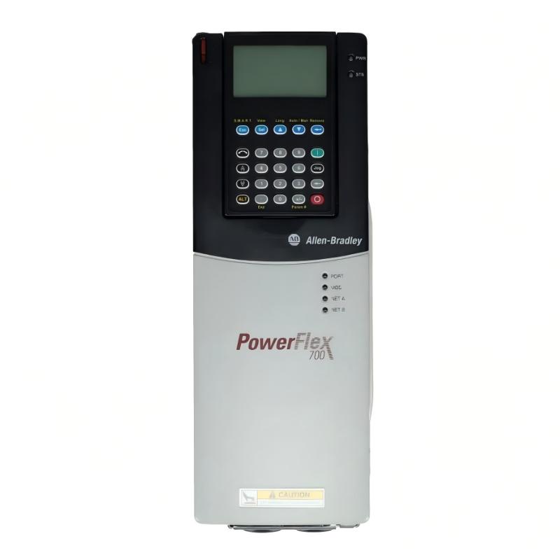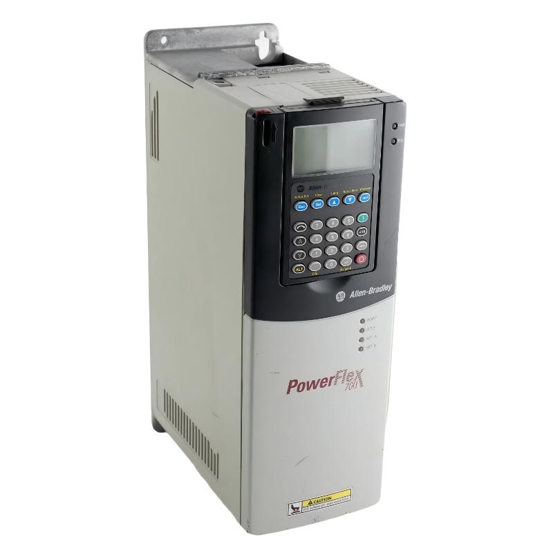
Allen Bradley 20BD5P0A3AYNAEC1 PowerFlex 700 AC Drive Installation Guide: Setup and Commissioning
Allen Bradley 20BD5P0A3AYNAEC1 PowerFlex 700 AC Drive installation requires correct power wiring, motor connection, parameter configuration, and commissioning procedures to achieve stable speed control and reliable industrial operation. In field applications, most startup issues are related to incorrect motor data, grounding problems, control wiring mistakes, or parameter mismatch rather than drive hardware failure.
Allen Bradley 20BD5P0A3AYNAEC1 PowerFlex 700 AC Drive Application
The Allen Bradley 20BD5P0A3AYNAEC1 is a PowerFlex 700 AC Drive designed for industrial motor control applications requiring adjustable speed operation, precise acceleration control, and reliable machine performance.
Typical applications include:
- Conveyor systems
- Pumps and fans
- Material handling equipment
- Packaging machinery
- Process automation systems
- Industrial production lines
- Machine motion control
As a variable frequency drive, the PowerFlex 700 controls motor speed and torque by regulating output frequency and voltage. Correct installation must consider the complete drive system:
Power Supply → AC Drive → Motor → Mechanical Load → Control System
A successful commissioning process depends on matching the drive parameters with the actual motor and application requirements.
Allen Bradley 20BD5P0A3AYNAEC1 Technical Installation Specifications
Before installation, verify the main electrical and mechanical specifications.
| Parameter | Specification |
|---|---|
| Manufacturer | Allen Bradley |
| Model | 20BD5P0A3AYNAEC1 |
| Product Type | PowerFlex 700 AC Drive |
| Drive Series | PowerFlex 700 |
| Input Voltage | 400/480 V AC Class |
| Frame Size | Frame 1 |
| Dimensions | 336 × 200 × 110 mm |
| Weight | 5.22 kg / 11.51 lb |
| Control Type | Adjustable Frequency Drive |
| Communication Capability | Network communication options available |
| Application | Industrial motor speed control |
The mechanical installation space should allow sufficient airflow around the drive. Poor ventilation can increase internal temperature and shorten component life.
Allen Bradley 20BD5P0A3AYNAEC1 Installation Preparation
Before mounting the PowerFlex 700 drive, inspect the installation environment and confirm:
- Correct supply voltage
- Suitable enclosure protection
- Proper grounding system
- Motor compatibility
- Correct cable selection
- Adequate ventilation space
- Stable control power supply
The installation area should be free from:
- Excessive dust
- Conductive contamination
- Corrosive gases
- Excessive vibration
- High humidity
Before wiring, verify that the incoming power source is isolated.
A common field mistake is connecting control wiring before confirming the power section, which can create unnecessary troubleshooting during startup.
Allen Bradley 20BD5P0A3AYNAEC1 Power Wiring Installation
Correct power wiring is critical for reliable AC Drive operation.
The basic power path is:
Three-Phase AC Supply → PowerFlex 700 Input Terminals → DC Bus → Motor Output Terminals → Motor
During installation, check:
- Input phase sequence
- Voltage rating
- Terminal torque
- Protective devices
- Ground conductor connection
- Motor cable insulation
The motor cable should be separated from sensitive control cables to reduce electromagnetic interference.
Improper grounding is one of the most common causes of:
- Communication interference
- Encoder signal problems
- Unexpected drive trips
- Control instability
Allen Bradley 20BD5P0A3AYNAEC1 Motor Connection Setup
The motor parameters must be entered correctly before commissioning.
Important motor data includes:
- Motor rated voltage
- Motor rated current
- Motor frequency
- Motor speed
- Motor power rating
- Acceleration time
- Deceleration time
Incorrect motor parameters may cause:
- Overcurrent trips
- Poor torque performance
- Motor overheating
- Unstable speed control
In practical commissioning, engineers should compare the motor nameplate values with the drive configuration instead of relying on default parameters.
Allen Bradley 20BD5P0A3AYNAEC1 Control Configuration and Setup
The PowerFlex 700 supports different control methods depending on the application.
The Setup process should confirm:
- Start/stop command source
- Speed reference source
- Digital input assignment
- Analog input scaling
- Communication settings
- Fault response configuration
A typical configuration sequence:
Hardware Installation → Parameter Setup → Motor Data Entry → Control Configuration → Test Run
Before connecting the drive to the complete production system, perform a local test run if possible.
Allen Bradley 20BD5P0A3AYNAEC1 Commissioning Procedure
During Commissioning, verify the drive response under controlled conditions.
Recommended checks:
| Test Item | Verification |
|---|---|
| Power-up status | No hardware fault |
| Display operation | Normal parameters shown |
| Motor rotation | Correct direction |
| Acceleration | Smooth ramp |
| Deceleration | No excessive current |
| Operating current | Within motor rating |
If the motor rotates in the wrong direction, correct the motor phase connection or command configuration.
Do not continue operation until the basic rotation and current behavior are confirmed.
Allen Bradley 20BD5P0A3AYNAEC1 Real Commissioning Case
In one field commissioning case, a PowerFlex 700 drive was installed on a conveyor system. The drive powered up normally, but the motor tripped during acceleration.
The initial assumption was that the AC Drive capacity was insufficient.
The engineer checked the operating data:
- Motor current during acceleration: 18 A
- Motor rated current: 12 A
- Acceleration time setting: 3 seconds
The investigation showed that the acceleration ramp was too aggressive for the mechanical load.
After increasing the acceleration time, the motor current dropped into the normal range and the drive operated correctly.
The issue was not a hardware failure but an application parameter mismatch.
Allen Bradley 20BD5P0A3AYNAEC1 Environmental Installation
Long-term PowerFlex 700 reliability depends heavily on installation conditions.
Monitor:
- Cabinet temperature
- Cooling airflow
- Fan operation
- Dust accumulation
- Cable arrangement
- Grounding quality
Avoid installing the drive near strong heat sources or equipment generating excessive electrical noise.
A properly installed AC Drive should maintain stable operation under normal load conditions without frequent thermal or electrical trips.
Allen Bradley 20BD5P0A3AYNAEC1 Installation Troubleshooting
| Observation | Initial Diagnostic Direction |
|---|---|
| Drive will not start | Control source and enable signal |
| Motor does not rotate | Output wiring and motor parameters |
| Overcurrent during startup | Acceleration settings and motor data |
| Drive overheats | Cooling and installation environment |
| Communication unavailable | Network settings and wiring |
| Unexpected trip | Fault history and application conditions |