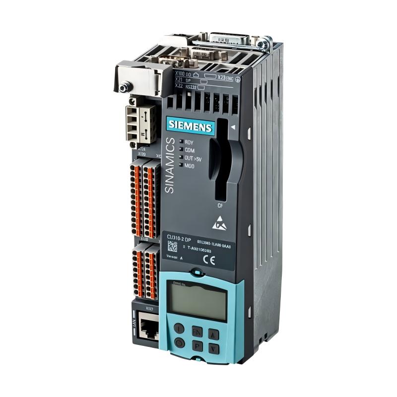
Siemens 6AG1040-1LA00-2AA0 SIPLUS S120 Control Unit Troubleshooting Guide (Fault Diagnosis)
Siemens 6AG1040-1LA00-2AA0 SIPLUS S120 Control Unit troubleshooting should begin with fault classification: communication, configuration, feedback, control supply, or drive-object problems. A control-unit replacement should normally be considered only after the surrounding system has been proven healthy.
A useful field-oriented approach is to reproduce the fault, identify the first abnormal signal, and then work upstream or downstream from that point.
Siemens 6AG1040-1LA00-2AA0 S120 Fault Symptoms
Typical symptoms can include:
- Drive system does not enable
- Axis remains stationary
- Communication becomes intermittent
- Drive objects report configuration errors
- Feedback values appear incorrect
- Fault returns after reset
One important distinction is whether the control unit itself is unavailable or whether it is correctly operating but reporting a problem originating elsewhere.
Siemens 6AG1040-1LA00-2AA0 Fault Diagnosis Thinking Process
Use this diagnostic chain:
Fault Appears
     |
     v
Is Control Unit Online?
     |
     +---- No ----> Check Power / Communication / Hardware
     |
    Yes
     |
     v
Are Drive Objects Healthy?
     |
     +---- No ----> Check Configuration / Parameters
     |
    Yes
     |
     v
Is Feedback Valid?
     |
     +---- No ----> Check Encoder / Wiring / Scaling
     |
    Yes
     |
     v
Check Motor and Mechanical Load
This approach avoids replacing expensive electronics simply because a drive fault appears on the HMI.
Siemens 6AG1040-1LA00-2AA0 Communication Fault Investigation
Consider a case where an S120 system intermittently disappeared from the engineering workstation.
Initial observations:
- Control cabinet power: Stable
- Control unit: Operating
- Network status: Intermittent
- Motor: Not yet enabled
The engineers monitored the communication connection rather than changing motor parameters.
They found that communication was lost when a nearby contactor switched.
The investigation then focused on:
- Cable routing
- Shield termination
- Grounding
- Separation from switching conductors
After rerouting the communication cable and correcting its shielding arrangement, the intermittent communication fault disappeared.
The important observation was that the fault occurred at a repeatable electrical event.
That timing provided more useful information than simply reading the displayed fault code.
Siemens 6AG1040-1LA00-2AA0 Configuration Fault Analysis
Another common S120 troubleshooting pattern occurs after component replacement.
Symptoms:
- Control unit powers up
- Communication is established
- Drive object remains unavailable
- Axis cannot be enabled
A useful comparison is:
| Diagnostic Area | Question |
| Hardware | Is the installed device correctly identified? |
| Topology | Does the project match the physical system? |
| Motor | Is the correct motor assigned? |
| Feedback | Is the encoder configured correctly? |
| Parameters | Were required settings restored? |
If the hardware has changed but the project configuration has not, the resulting problem may look like a hardware fault even though the electronics are healthy.
Siemens 6AG1040-1LA00-2AA0 Feedback Fault Diagnosis
Feedback problems deserve separate attention because they can produce confusing motion symptoms.
Possible observations:
- Commanded speed is stable
- Actual speed fluctuates
- Position value jumps
- Axis refuses to enable
Engineers should compare the command signal with the actual feedback value.
For example:
Command Speed: 1000 rpm
Actual Speed: 995 → 1008 → 972 → 1015 rpm
If the mechanical speed is physically stable but the feedback value fluctuates significantly, inspect:
- Encoder wiring
- Connector contacts
- Shielding
- Feedback device
- Configuration and scaling
Do not immediately conclude that the S120 control unit has failed.
Siemens 6AG1040-1LA00-2AA0 Control Unit Repair Strategy
When troubleshooting reaches the hardware level, divide the problem into three questions:
Can the control unit power up?
Can it communicate correctly?
Can it correctly exchange data with the drive objects?
If all three functions are normal, the problem may be elsewhere in the system.
If the control unit repeatedly fails despite:
- Verified control power
- Correct wiring
- Correct configuration
- Known-good communication infrastructure
then hardware replacement becomes a more reasonable engineering decision.
Before replacement, save:
- Fault history
- Parameter data
- Project configuration
- Diagnostic information
This makes post-repair comparison much easier.
Siemens 6AG1040-1LA00-2AA0 Troubleshooting Recovery and Validation
After correcting the fault, perform a controlled restart.
Verify:
- Control unit startup
- Communication stability
- Drive object status
- Feedback values
- Enable sequence
- Low-speed operation
- Normal machine cycle
Do not validate a repair only by confirming that the alarm disappeared.
A proper Siemens 6AG1040-1LA00-2AA0 Troubleshooting procedure ends when the machine demonstrates stable operation under its normal production sequence.
Siemens 6AG1040-1LA00-2AA0 Common Fault Diagnosis Patterns
Communication Interruption
Symptoms: Control system intermittently loses the drive.
Check: Power, communication cable, shielding, connector condition, and network topology.
Drive Object Configuration Error
Symptoms: Hardware is online but an axis cannot be enabled.
Check: Hardware configuration, topology, motor assignment, and parameter consistency.
Unstable Feedback
Symptoms: Speed or position values fluctuate unexpectedly.
Check: Encoder wiring, shielding, connectors, feedback configuration, and signal quality.
Enable Failure
Symptoms: Drive remains inhibited despite a valid motion command.
Check: Enable conditions, interlocks, drive status, safety chain, and configuration.
Siemens 6AG1040-1LA00-2AA0 Long-Term Maintenance and Fault Prevention
For long-term S120 reliability:
- Keep a verified parameter backup
- Document hardware changes
- Maintain communication cable routing
- Inspect connectors during scheduled maintenance
- Record recurring fault patterns
- Preserve commissioning measurements
The most useful maintenance baseline is not simply a list of fault codes. Record normal values for communication status, feedback behavior, motor current, and operating sequence.
When a future deviation appears, engineers can compare the new condition against a known-good machine state.
The practical rule is simple:
Do not diagnose the Siemens 6AG1040-1LA00-2AA0 control unit in isolation. Trace the complete S120 control path and identify the first abnormal condition before replacing hardware.
Recommended diagnostic sequence:
Control power → Communication → Hardware configuration → Drive objects → Feedback → Enable chain → Motor response → Final system validation