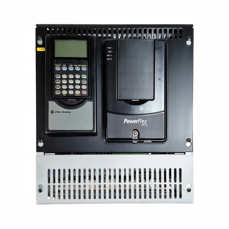
Allen-Bradley 20P21AD207RA0NNN PowerFlex DC Drive Installation Guide (Wiring & Commissioning)
Allen-Bradley 20P21AD207RA0NNN PowerFlex DC Drive installation problems are usually caused by incorrect motor field wiring, improper armature configuration, inaccurate motor parameters, or incomplete commissioning procedures rather than drive hardware failure. In industrial DC motor control systems, a drive can power up normally while the motor still performs poorly because the feedback, current regulation, and field excitation settings are not correctly matched.
The Allen-Bradley 20P21AD207RA0NNN PowerFlex DC Drive is designed for industrial DC motor applications requiring accurate speed regulation, reliable torque control, and flexible integration with automation systems. It is commonly applied in manufacturing equipment, material handling systems, winding machines, test stands, and process lines where precise DC motor control is required.
Allen-Bradley 20P21AD207RA0NNN PowerFlex DC Drive Application Overview
The PowerFlex DC Drive controls the energy supplied to a DC motor by regulating armature voltage, field excitation, and feedback signals.
Typical system structure:
AC Power Supply||Allen-Bradley 20P21AD207RA0NNN PowerFlex DC Drive||DC Motor Armature + Field Circuit||Industrial Mechanical Load
Main functions:
- DC motor speed control
- Torque regulation
- Armature current management
- Field excitation control
- Industrial automation integration
Typical applications:
- Paper processing equipment
- Extrusion machines
- Rolling equipment
- Conveyors
- Winding and unwinding systems
Unlike simple motor starters, DC drives require detailed commissioning because motor performance depends on multiple parameters:
- Armature voltage
- Armature current
- Field current
- Feedback type
- Acceleration profile
In one manufacturing line upgrade project, engineers installed an Allen-Bradley 20P21AD207RA0NNN PowerFlex DC Drive for a large DC motor replacement.
During commissioning:
- Drive display: Normal
- Control signals: Available
- Motor rotation: Unstable
The initial assumption was a mechanical load problem.
The engineering team performed a complete investigation:
- Checked motor nameplate data
- Verified armature connections
- Measured field current
- Reviewed drive tuning parameters
Measured condition:
Before correction:
- Input power: Normal
- Control command: Correct
- Field current: Lower than expected
- Motor speed: Fluctuating
Further analysis showed that the field current parameter did not match the motor requirements.
After correcting the field configuration:
- Motor speed stabilized
- Torque response improved
- Production equipment operated normally
The issue was caused by commissioning settings rather than drive failure.
Allen-Bradley 20P21AD207RA0NNN PowerFlex DC Drive Installation Preparation and System Planning
Before installing the PowerFlex DC Drive, engineers should evaluate the complete motor control system.
Preparation requirements:
- Confirm DC motor specifications
- Verify armature voltage rating
- Check field winding requirements
- Prepare feedback devices
- Review protection settings
Installation checklist:
| Inspection Item | Engineering Requirement |
|---|---|
| Motor rating | Match drive configuration |
| Armature wiring | Correct polarity and connection |
| Field circuit | Correct excitation wiring |
| Feedback device | Compatible with drive settings |
| Grounding | Proper protective grounding |
A common field mistake is installing a DC drive using only motor voltage information.
Engineers must also verify:
- Rated current
- Field current
- Feedback method
- Application load characteristics
Incorrect motor data may result in:
- Excessive current
- Poor speed regulation
- Motor overheating
- Drive protection trips
Allen-Bradley 20P21AD207RA0NNN PowerFlex DC Drive Wiring Installation
Correct wiring is critical for DC motor performance.
Armature Circuit Wiring Inspection
Verify:
- Positive and negative armature terminals
- Cable size
- Connection polarity
Incorrect armature wiring can cause:
- Reverse rotation
- Excessive current
- Motor startup failure
Field Circuit Connection Verification
Check:
- Field supply connection
- Field polarity
- Field current feedback
A weak or incorrect field connection may cause:
- Speed instability
- Reduced torque
- Overspeed conditions
Feedback Device Wiring Check
Verify:
- Encoder or tachometer connection
- Signal polarity
- Feedback scaling
During one commissioning case:
Initial condition:
- Drive enabled correctly
- Motor started but speed fluctuated
Engineering measurements:
- Armature voltage: Normal
- Field current: Stable
- Speed feedback: Incorrect
Inspection found:
- Feedback polarity was reversed
After correction:
- Speed loop became stable
- Motor followed speed commands accurately
Allen-Bradley 20P21AD207RA0NNN Setup and Commissioning Configuration
The commissioning stage determines DC motor performance.
Important configuration areas:
- Motor rated voltage
- Motor rated current
- Field parameters
- Feedback selection
- Speed regulation settings
Typical commissioning logic:
IF Motor_Data = CorrectAND Feedback = ValidAND Field_Current = NormalTHENEnable_DC_Motor_Control
Engineers should verify:
- No drive faults
- Stable current regulation
- Correct rotation direction
- Smooth acceleration
A practical commissioning approach is to adjust one parameter group at a time and record motor response.
This helps identify whether the issue comes from:
- Motor wiring
- Drive configuration
- Feedback system
- Mechanical load
Allen-Bradley 20P21AD207RA0NNN Commissioning Validation and Performance Testing
Final testing should verify the complete DC drive system.
Motor Performance Test
Check:
- Starting torque
- Speed response
- Current stability
- Load operation
Protection Function Test
Verify:
- Overcurrent protection
- Field loss detection
- Drive fault response
Example commissioning results:
Before optimization:
- Speed oscillation occurred
- Motor response was unstable
- Production speed fluctuated
After adjustment:
- Stable speed regulation
- Smooth acceleration
- Reliable machine operation
A successful Allen-Bradley 20P21AD207RA0NNN PowerFlex DC Drive installation requires correct motor data, accurate wiring, and practical commissioning validation.