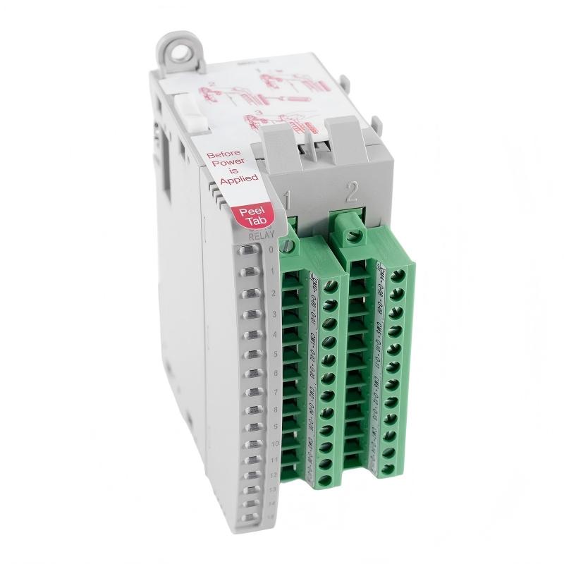
Allen-Bradley 2085-OW16 Micro800 Relay Output Module Installation Guide (Wiring & Commissioning)
Allen-Bradley 2085-OW16 Micro800 16-point relay output module installation problems are most often caused by incorrect output wiring, unsuitable load characteristics, common-terminal mistakes, or incorrect Micro800 system configuration. A relay output module may show normal controller communication while an external contactor, solenoid, lamp, or relay still fails to operate because the field circuit has not been wired or configured correctly.
The Allen-Bradley 2085-OW16 Micro800 16-point Relay Output Module is used with Micro800 control systems to provide multiple relay-switched outputs for industrial field devices. Because relay outputs are commonly connected to inductive loads, commissioning should include both electrical verification and actual load testing.
Allen-Bradley 2085-OW16 Micro800 Relay Output Module Application
The 2085-OW16 extends the output capability of a Micro800 PLC system.
Typical architecture:
Micro800 Controller
        |
        |
2085-OW16 Relay Output Module
        |
        +----------+----------+
        |          |          |
     Contactor   Solenoid    Relay
        |          |          |
        +----------+----------+
                   |
              Machine Equipment
Typical applications include:
- Machine automation
- Conveyor systems
- Packaging equipment
- Pump control
- Valve control
- General-purpose actuator switching
Relay outputs are particularly useful when the field device requires a switching arrangement that differs from a simple low-voltage transistor output.
Common loads include:
- Contactors
- Control relays
- Solenoid valves
- Indicator devices
- Small auxiliary actuators
In one machine retrofit, engineers added a 2085-OW16 to provide additional actuator outputs.
During commissioning, the PLC program correctly activated the output bits, but two pneumatic valves did not respond.
The investigation found:
- PLC logic: Correct
- Output status: Correct
- Field power: Available
- Valve circuit: Incorrectly referenced
After correcting the field wiring, both valves operated normally.
The module itself had not failed.
Allen-Bradley 2085-OW16 Installation Preparation and System Planning
Before installing the relay output module, verify the complete Micro800 architecture.
Review:
- Controller compatibility
- Module position
- Output allocation
- Field load voltage
- Load current
- Wiring diagram
A practical preparation table:
| Inspection Item | Engineering Check |
|---|---|
| Micro800 system | Confirm compatible expansion arrangement |
| Output channels | Assign each field device |
| Load voltage | Verify against connected equipment |
| Load current | Confirm relay contact suitability |
| Common wiring | Check circuit reference |
| Protection | Consider suppression for inductive loads |
Do not determine load compatibility from voltage alone.
A contactor coil may operate at the expected voltage but still create a substantial switching transient. Suppression and circuit protection should therefore be considered during the design stage.
Allen-Bradley 2085-OW16 Relay Output Module Wiring Installation
The physical wiring should be checked channel by channel.
Allen-Bradley 2085-OW16 Output Wiring
For each output:
- Identify the correct channel
- Verify the common connection
- Confirm field supply
- Confirm actuator wiring
- Check terminal tightness
A useful field test is to trace the circuit physically rather than relying only on the electrical drawing.
PLC Output Command
       ↓
2085-OW16 Channel
       ↓
Relay Contact
       ↓
Field Supply
       ↓
Load
       ↓
Return Path
If any point in this chain is open, the actuator will not operate.
Allen-Bradley 2085-OW16 Inductive Load Wiring and Protection
Relay outputs are frequently connected to inductive devices.
Examples:
- AC contactor coils
- Solenoid valves
- Auxiliary relays
When these loads switch off, stored energy can produce voltage transients.
During installation, engineers should evaluate whether appropriate suppression is required for the specific load.
Potential symptoms of poor load protection include:
- Contact wear
- Electrical noise
- Intermittent PLC behavior
- Premature relay failure
In one field installation, a contactor repeatedly caused unrelated controller communication disturbances when switched.
The output channel itself tested normally.
After inspecting the contactor circuit, engineers found that the coil suppression arrangement was inadequate. Correcting the suppression significantly reduced the electrical disturbance.
Allen-Bradley 2085-OW16 Micro800 System Configuration and Setup
The physical output channel must correspond with the Micro800 program.
Verify:
- Expansion module recognition
- Output addressing
- Channel assignment
- Controller configuration
- Output logic
A simple diagnostic model is:
IF PLC_Output_Bit = ON
AND 2085-OW16_Channel = ON
AND Field_Power = Present

THEN

Load_Should_Operate
If the PLC bit is ON but the field device does not operate, the next diagnostic point should be the physical output circuit.
This prevents unnecessary changes to the PLC program.
Allen-Bradley 2085-OW16 Setup and Commissioning Procedure
Commissioning should start with low-risk functional checks.
First verify:
- Controller communication
- Module recognition
- Output status
- Field voltage
Then test individual channels.
For example:
Channel 0 → Test
Channel 1 → Test
Channel 2 → Test
...
Channel 15 → Test
Record any channel that behaves differently.
If channels 0–14 operate correctly but channel 15 does not, compare that channel with a known-good output rather than immediately replacing the complete module.
Allen-Bradley 2085-OW16 Commissioning Validation and Load Testing
A proper commissioning test should include actual field loads.
Verify:
- Output activation
- Output release
- Load response
- Machine sequence
- Interlocks
A field commissioning example involved a conveyor system where the output module controlled several motor contactors.
Initial test:
- PLC output commands: Correct
- Contactors: Intermittent
- Machine sequence: Failed during repeated cycling
Engineers monitored the output circuit during approximately 100 switching cycles.
The fault appeared only after repeated operation.
Inspection found a loose field terminal that became electrically unstable because of mechanical vibration.
After tightening and securing the connection:
- Switching became repeatable
- Contactor operation stabilized
- Conveyor sequence completed normally
This illustrates why Setup / Commissioning should include repeated-cycle testing rather than a single successful output command.