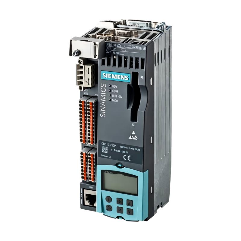
Siemens 6AG1040-1LA00-2AA0 SIPLUS S120 Control Unit Installation Guide (Setup & Commissioning)
Siemens 6AG1040-1LA00-2AA0 SIPLUS S120 Control Unit installation problems are most often linked to incorrect control-unit mounting, communication wiring, incomplete parameterization, or inconsistent drive-system configuration rather than an immediate hardware failure. For an S120 system, the control unit is the point where drive objects, communication, feedback, and motion-control parameters come together, so commissioning should begin with system architecture rather than simply applying power.
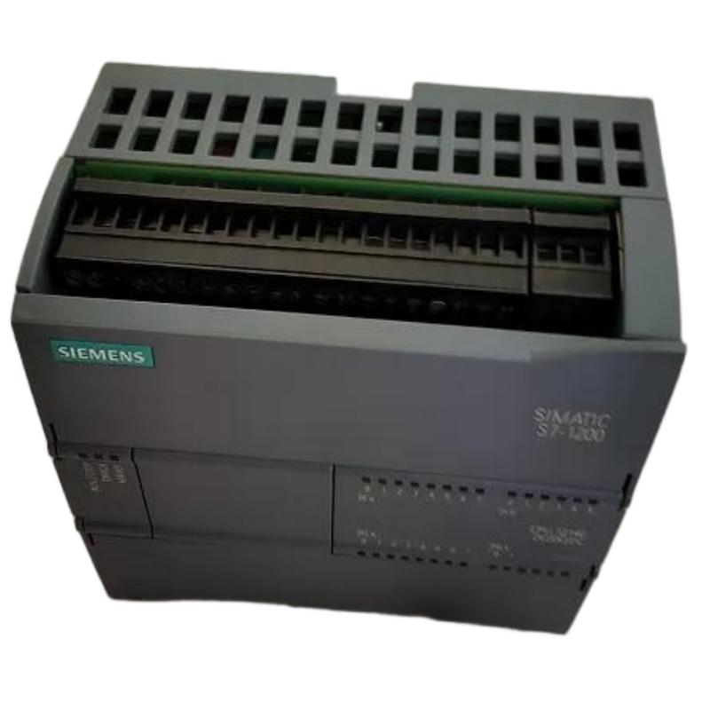
The Siemens 6AG1040-1LA00-2AA0 SIPLUS S120 Control Unit is intended for demanding industrial drive applications where reliable control of SINAMICS S120 components is required. Its role makes correct hardware identification, network configuration, parameter handling, and commissioning especially important.
Siemens 6AG1040-1LA00-2AA0 SIPLUS S120 Control Unit Application
A typical S120 architecture can be organized as:
PLC / Motion Controller
          |
          |
Industrial Communication
          |
          |
SIPLUS S120 Control Unit
          |
          +----------------+
          |                |
      Drive Objects     Feedback
          |                |
          +--------+-------+
                   |
             Power Section
                   |
                 Motor
The control unit coordinates the drive system rather than functioning as an isolated controller.
Typical applications include:
- Servo and motion-control machines
- High-performance production equipment
- Packaging machinery
- Material handling systems
- Machine-tool applications
- Multi-axis drive systems
In practical engineering work, the control unit should be treated as the central commissioning point for the S120 system.
Siemens 6AG1040-1LA00-2AA0 Installation Preparation
Before mounting the control unit, confirm the complete drive architecture.
Review:
- Hardware order numbers
- Drive topology
- Control supply
- Communication connections
- Motor and feedback arrangement
- Existing parameter backup
A useful preparation record is:
| Item | Verification |
|---|---|
| Control Unit | Correct hardware identified |
| Power supply | Stable control voltage |
| Communication | Correct interface and cable |
| Drive topology | Matches engineering project |
| Motor data | Available from nameplate |
| Feedback | Correct encoder information |
| Parameters | Backup available |
Do not begin commissioning by changing parameters randomly. If an existing machine is being repaired, preserving the original parameter set can save considerable diagnostic time.
Siemens 6AG1040-1LA00-2AA0 SIPLUS Control Unit Mounting
Mechanical installation should be completed before connecting the control electronics.
Check:
- Correct mounting position
- Secure mechanical fixing
- Connector alignment
- Clearance around the unit
- Cabinet environmental conditions
Because SIPLUS equipment is intended for demanding industrial environments, the installation should still follow the actual application's temperature, contamination, vibration, and cabinet requirements.
One commissioning team once replaced an S120 control assembly after repeated communication interruptions.
The replacement initially showed the same symptoms.
The investigation showed:
- Control unit installation: Correct
- Communication cable: Correct
- Power supply: Stable
- Cabinet vibration: Excessive
After correcting the mechanical mounting condition, communication stability improved substantially.
The important engineering lesson was that replacing the electronic module did not address the physical installation problem.
Siemens 6AG1040-1LA00-2AA0 Wiring and Communication Setup
Communication wiring should be checked before software commissioning.
Verify:
- Connector seating
- Cable routing
- Shielding
- Network topology
- Control supply connections
Keep communication cables away from high-current motor cables where practical.
A noisy control cabinet can produce symptoms that look like software or drive faults.
Typical diagnostic logic:
IF Control_Power = Stable
AND Communication = Active
AND Drive_Topology = Correct

THEN

Continue_S120_Commissioning
If communication is unstable, do not immediately modify motor-control parameters. First establish a reliable communication layer.
Siemens 6AG1040-1LA00-2AA0 System Configuration and Setup
The system configuration stage should establish the relationship between the control unit, drive objects, motors, and feedback devices.
Important engineering data includes:
- Motor identification
- Drive object assignment
- Encoder configuration
- Communication addresses
- Operating mode
- Control interface
The configuration should correspond to the actual installed hardware.
For an existing machine, compare:
Original project → Current hardware → Actual wiring → Online configuration
Any mismatch should be resolved before motion testing.
Siemens 6AG1040-1LA00-2AA0 Setup and Commissioning Validation
Commissioning should progress from low-risk checks toward actual motion.
A practical sequence is:
Control Power
      ↓
Communication
      ↓
Hardware Identification
      ↓
Drive Object Configuration
      ↓
Feedback Verification
      ↓
Enable Signal
      ↓
Low-Speed Motion
      ↓
Loaded Machine Test
During the first movement test, observe:
- Motor direction
- Speed feedback
- Actual current
- Fault messages
- Mechanical response
A field commissioning example involved a servo axis that reached approximately 20% commanded speed but immediately generated a tracking-related alarm.
The team did not replace the control unit.
Instead, they compared:
- Commanded speed
- Actual speed
- Encoder feedback
- Mechanical brake release
The encoder feedback was delayed because the brake-release sequence was incomplete.
After correcting the sequence, the axis accelerated normally.
This is typical of good Fault Diagnosis practice: establish which signal is wrong before replacing hardware.
Siemens 6AG1040-1LA00-2AA0 Final Commissioning Checks
Before handing the machine to production, verify:
- No active drive faults
- Stable communication
- Correct motor direction
- Valid feedback
- Normal acceleration and deceleration
- Correct emergency-stop behavior
- Repeatable restart behavior
Record the final parameter configuration.
This creates a useful baseline for future Troubleshooting and maintenance work.