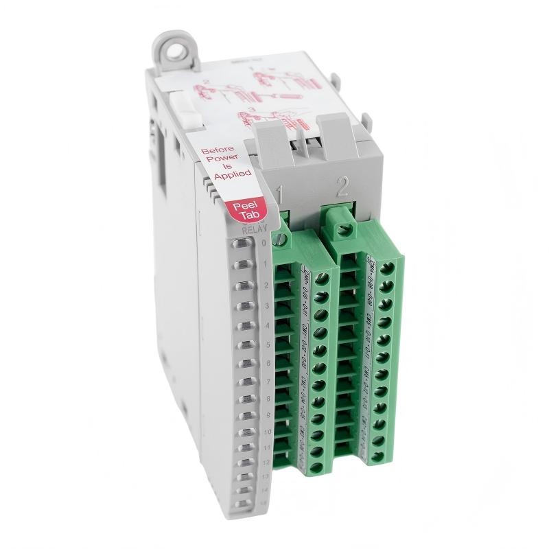
Allen-Bradley 2085-OW16 Micro800 Relay Output Module Troubleshooting Guide (Fault Diagnosis)
Allen-Bradley 2085-OW16 troubleshooting should distinguish between a PLC command problem, relay output problem, field power problem, and actuator problem. When a relay output appears inactive, replacing the module is usually not the first diagnostic action.
The fastest approach is to determine where the electrical signal stops.
Allen-Bradley 2085-OW16 Relay Output Fault Symptoms
Typical symptoms include:
- Output channel does not switch
- Actuator remains OFF
- Load operates intermittently
- PLC output bit changes but field device does not respond
- Machine sequence stops at a particular output
Consider a field case involving a valve control station.
The operator reported:
Valve command was ON, but the valve remained closed.
Initial assumptions included:
- Failed output relay
- Failed solenoid
- PLC programming error
The engineering team tested the circuit in that order instead of replacing the module.
Allen-Bradley 2085-OW16 Fault Diagnosis Signal Path
The diagnostic path was:
PLC Logic
   ↓
Output Bit
   ↓
2085-OW16 Channel
   ↓
Relay Contact
   ↓
Field Voltage
   ↓
Solenoid Coil
   ↓
Return Circuit
The PLC output bit changed correctly.
The module channel indication also responded.
That shifted the investigation toward the field circuit.
This distinction is important because a functioning output indication does not automatically prove that the complete actuator circuit is electrically healthy.
Allen-Bradley 2085-OW16 Relay Contact Fault Investigation
Engineers measured the field circuit with the output commanded ON.
Observed condition:
- PLC command: ON
- Module status: ON
- Supply voltage: Present
- Voltage at solenoid: 0 V
The diagnostic question became:
Where is the voltage disappearing?
The team checked the relay contact path and discovered an incorrectly wired common connection.
After correcting the common circuit:
- Solenoid voltage returned
- Valve energized
- Machine sequence resumed
The 2085-OW16 had been correctly receiving and executing the command.
Allen-Bradley 2085-OW16 Intermittent Output Fault Analysis
A different failure pattern can be more difficult.
Suppose the actuator works during initial testing but fails after several hours.
The diagnostic approach should include:
- Terminal temperature
- Connection stability
- Load current
- Mechanical vibration
- Switching frequency
For example:
Initial Test
     ↓
Output Normal
     ↓
Repeated Switching
     ↓
Fault Appears
     ↓
Check Thermal / Mechanical Conditions
If the fault correlates with machine vibration or temperature, inspect the physical wiring before changing the control program.
Allen-Bradley 2085-OW16 Relay Output Overload and Load Fault Diagnosis
When a relay output repeatedly fails under a particular load, inspect the load itself.
Possible causes:
- Excessive coil current
- Shorted actuator
- Incorrect field voltage
- Switching transient
- Damaged contactor coil
A useful measurement is the actual load current.
For example:
Expected Load Current → Compare → Measured Load Current
If measured current is significantly different from the expected value, investigate the field device before concluding that the output module is defective.
Allen-Bradley 2085-OW16 Troubleshooting Repair and Recovery
A practical repair sequence is:
PLC command verification → Module status → Field voltage → Relay contact → Load measurement → Wiring inspection → Final machine test
After corrective work, test both:
- Output activation
- Output release
The second test is important for relay-controlled equipment because a device that turns ON correctly may still have a problem when the circuit is released.
Allen-Bradley 2085-OW16 Common Fault Diagnosis Patterns
Output Command Active but Load OFF
Check:
- Field supply
- Common connection
- Relay contact path
- Load wiring
Output Works Intermittently
Check:
- Terminal tightness
- Vibration
- Load current
- Contact condition
- Field power stability
Output Causes Electrical Disturbance
Check:
- Inductive load
- Suppression
- Cable routing
- Grounding
One Channel Behaves Differently
Check:
- Channel wiring
- Connected load
- Terminal condition
- Output configuration
Do not replace the entire module until the affected channel has been compared with a known-good channel under equivalent conditions.
Allen-Bradley 2085-OW16 Long-Term Maintenance Strategy
For reliable Micro800 relay output operation:
- Keep output wiring clearly identified
- Inspect terminals during scheduled maintenance
- Monitor unusual actuator behavior
- Check inductive-load protection
- Record recurring output faults
- Retest repaired circuits under normal machine cycles
The most useful maintenance record is a baseline showing which output controls which actuator and what normal electrical behavior looks like.
When a fault occurs later, engineers can compare the abnormal channel with its original operating condition.
Practical rule: When performing Allen-Bradley 2085-OW16 Troubleshooting and Fault Diagnosis, trace the signal from the Micro800 PLC output command to the final load. If the command is correct, determine where the electrical path stops before replacing the relay output module.