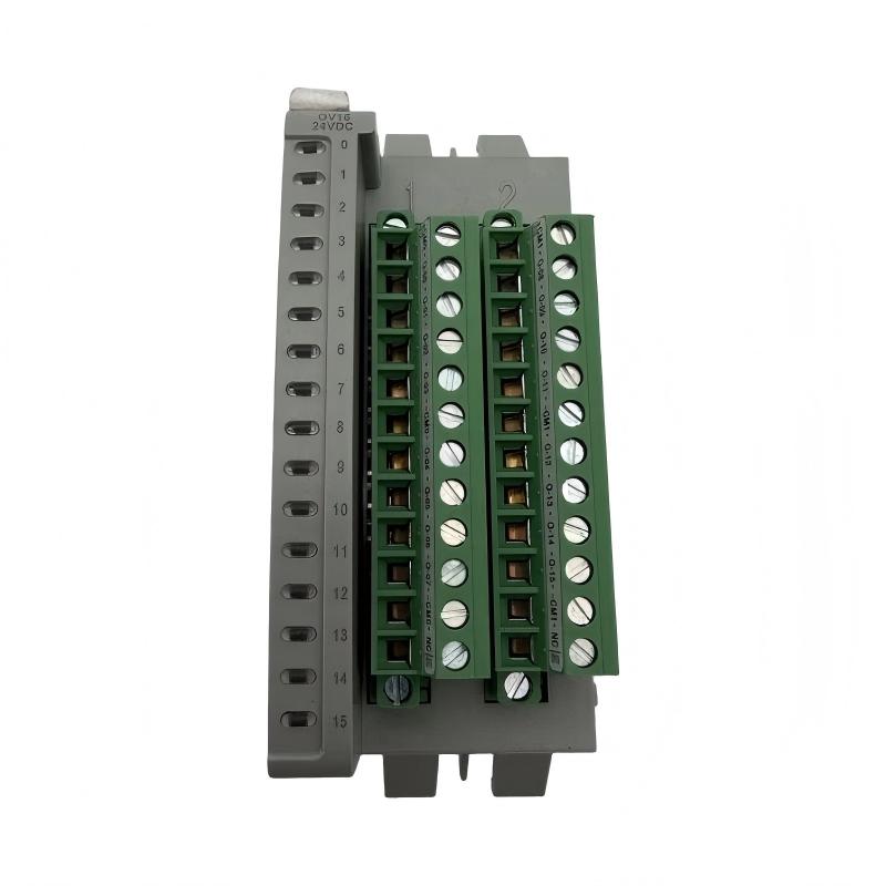
Allen-Bradley 2085-OV16 Micro800 Sink Output Module Troubleshooting Guide (Fault Diagnosis)
Allen-Bradley 2085-OV16 troubleshooting should focus on the complete DC output circuit, including PLC command, output channel, field power, polarity, and load condition. Sink output faults are frequently caused by wiring and load issues because the module depends on correct current flow through the external device.
Allen-Bradley 2085-OV16 Sink Output Module Fault Symptoms
Common symptoms include:
- Output channel does not activate
- Solenoid valve remains OFF
- Indicator lamp does not illuminate
- Output works only occasionally
- Multiple outputs fail after wiring changes
Field case:
A machine using a Micro800 controller with a 2085-OV16 module experienced several inactive pneumatic outputs after electrical maintenance.
Initial observations:
- PLC program running normally
- Controller communication normal
- Output commands generated correctly
The maintenance team suspected:
- Damaged output transistor
- Failed module
- PLC program problem
Engineers started diagnosis from the electrical circuit.
Allen-Bradley 2085-OV16 Fault Diagnosis Process and Signal Analysis
Troubleshooting path:
PLC Logic
    |
    |
Output Command
    |
    |
2085-OV16 Channel
    |
    |
Field Load
    |
    |
24VDC Supply
Engineers checked:
- PLC output status
- Module channel indication
- Output terminal voltage
- Field device condition
Results:
- PLC command: Correct
- Module status: Active
- Load voltage: Missing
The fault existed in the external DC circuit.
Allen-Bradley 2085-OV16 Output Channel Wiring Fault Investigation
Measurements:
Before repair:
- Control voltage: 24 VDC
- Output command: ON
- Valve coil voltage: 0 V
Engineers inspected:
- Terminal blocks
- Device polarity
- Common wiring
- Field power distribution
The investigation found:
- The 0V reference for the output group was disconnected during cabinet modification.
Because the 2085-OV16 is a sinking output device, the missing reference prevented current flow through the load.
After restoring the reference connection:
- Output current returned
- Valves activated correctly
- Machine operation recovered
Allen-Bradley 2085-OV16 Overload and Short Circuit Fault Diagnosis
Another common failure pattern is output overload.
Possible causes:
- Shorted solenoid coil
- Incorrect load selection
- Damaged field cable
- Excessive switching frequency
Diagnostic method:
Measure:
- Load resistance
- Operating current
- Output behavior during activation
Example:
Normal condition:
- Valve coil current: Expected range
Fault condition:
- Current significantly increased
- Output protection activated
The correct action is repairing the external load before returning the output channel to service.
Allen-Bradley 2085-OV16 Root Cause Analysis and Recovery
A complete Fault Diagnosis process should identify why the failure occurred.
Example:
Original condition:
- Correct polarity
- Stable 24 VDC supply
- Normal output switching
Failure condition:
- Cabinet modification changed field wiring
- Output reference disconnected
- Actuators stopped responding
Engineering conclusion:
The Micro800 output module was operating correctly.
The failure was caused by the external wiring change.
Allen-Bradley 2085-OV16 Troubleshooting Repair and System Recovery
Corrective actions:
Electrical Circuit Repair
Performed:
- Restored DC reference connection
- Checked output wiring
- Verified polarity
Functional Testing
Completed:
- Individual output test
- Automatic machine cycle test
- Repeated switching test
Final results:
Before repair:
- Multiple actuators unavailable
- Production cycle interrupted
After repair:
- Stable DC output switching
- Reliable actuator operation
- Normal machine production restored
Allen-Bradley 2085-OV16 Common Fault Diagnosis Methods
Output Command Active but Device OFF
Check:
- Load polarity
- 24 VDC supply
- 0V reference
- Field wiring
Output Intermittent During Operation
Check:
- Terminal tightness
- Cable condition
- Vibration effects
- Power stability
Output Channel Protection Activation
Check:
- Load current
- Short circuit condition
- Inductive protection
- Device compatibility
All Outputs Fail Together
Check:
- Module power supply
- Common wiring
- Controller communication
- Configuration
Allen-Bradley 2085-OV16 Long-Term Maintenance Strategy
For reliable Micro800 sink output operation:
- Maintain updated wiring drawings
- Label output channels clearly
- Inspect DC connections regularly
- Monitor actuator current changes
- Check inductive load protection
- Record output fault history
A practical engineering rule:
When troubleshooting an Allen-Bradley 2085-OV16 Micro800 Sink Output Module fault, verify current flow through the complete DC circuit before replacing the output module.
Recommended troubleshooting sequence:
PLC command check → Module status → 24VDC verification → Polarity inspection → Load measurement → Wiring correction → Final machine test.