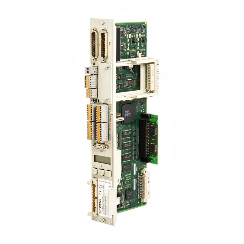
Siemens 6SN1118-0NH01-0AA1 Dual-Axis Control Loop Module Installation Guide, Setup and Commissioning
The Siemens 6SN1118-0NH01-0AA1 is a SIMODRIVE 611 dual-axis control loop module used to control two drive axes within a Siemens SIMODRIVE system. During installation and commissioning, the most important checks are correct module positioning, bus connections, axis configuration, feedback assignment, and compatibility with the associated power modules and motor system.
Siemens 6SN1118-0NH01-0AA1 Installation Guide and Module Function
The 6SN1118-0NH01-0AA1 belongs to the SIMODRIVE 611 drive system and provides control-loop functions for two axes. It is installed as part of a modular drive system rather than operated as an independent PLC controller.
Typical applications include:
- CNC machine tools
- Machine-tool feed axes
- Automated production equipment
- Multi-axis positioning systems
- Servo and spindle-related drive systems
- Retrofitting older SIMODRIVE installations
Because the module works together with other SIMODRIVE components, commissioning should always consider the complete drive configuration.
6SN1118-0NH01-0AA1 System Configuration Before Installation
Before mounting the module, verify the complete drive hardware arrangement.
Important items include:
| Check Item | Verification |
|---|---|
| Module | Siemens 6SN1118-0NH01-0AA1 |
| Function | Dual-axis control loop |
| Drive Platform | SIMODRIVE 611 |
| Axis Quantity | 2 control axes |
| Power Module | Compatible SIMODRIVE power section |
| Motor | Compatible servo motor / drive motor |
| Feedback | Correct encoder or motor feedback |
| Control System | Compatible CNC / machine controller |
| Bus/Backplane | Correct module interconnection |
| Cooling | Cabinet airflow and heat dissipation |
The module should not be selected only according to the number of axes. The control-loop electronics, power section, motor type, feedback system, and CNC configuration must form a compatible system.
Installing the Siemens 6SN1118-0NH01-0AA1 Control Loop Module
Before installation, disconnect the system from hazardous power and follow the machine manufacturer's lockout and discharge procedures.
Inspect the module for:
- Damaged connectors
- Bent contacts
- Contamination
- Signs of overheating
- Loose mechanical hardware
- Damaged PCB areas
Install the module in the designated SIMODRIVE position and ensure that it is properly seated in the system assembly.
Poor mechanical seating can create intermittent communication or control problems that may initially look like an electronic failure.
6SN1118-0NH01-0AA1 Wiring and Feedback Connections
The control-loop module depends heavily on correct feedback information.
When connecting the associated drive system, separate low-level feedback wiring from high-current motor and power conductors wherever possible.
Check:
- Feedback connector seating
- Encoder cable continuity
- Shield termination
- Connector pin assignment
- Motor-axis assignment
- Feedback polarity
- Cable condition
Do not change feedback wiring simply because an axis rotates in the wrong direction. First confirm the actual motor and encoder configuration against the machine documentation.
An incorrect feedback assignment can produce a dangerous condition because the control system may interpret actual movement incorrectly.
Siemens 6SN1118-0NH01-0AA1 Setup and Axis Configuration
After hardware installation, the two control-loop channels need to be correctly assigned within the SIMODRIVE system configuration.
The commissioning engineer should verify:
- Correct module recognition.
- Correct axis assignment.
- Correct motor data.
- Correct feedback configuration.
- Correct current-loop parameters.
- Correct speed-loop parameters.
- Correct direction of rotation.
- Correct software limits and machine interlocks.
The first test should normally be performed at low speed with the machine mechanically safe.
A successful commissioning sequence should demonstrate that the commanded movement and actual feedback agree.
Dual-Axis Commissioning Strategy for 6SN1118-0NH01-0AA1
Because this is a dual-axis control-loop module, testing both channels separately is useful.
For example:
Axis 1: low-speed jog → feedback verification → acceleration test → stop
Axis 2: low-speed jog → feedback verification → acceleration test → stop
Only after both axes operate independently should simultaneous two-axis movement be tested.
This approach makes Fault Diagnosis much easier because an axis-specific problem can be isolated before both channels interact through the machine control system.
Typical Siemens 6SN1118-0NH01-0AA1 Commissioning Case
Consider an older CNC machine equipped with two feed axes. After replacing a control-loop module, Axis 1 operates correctly while Axis 2 produces an unstable actual-speed signal.
A typical field diagnostic measurement might show:
| Measurement | Axis 1 | Axis 2 |
|---|---|---|
| Commanded speed | 500 rpm | 500 rpm |
| Actual speed | 498–502 rpm | 430–570 rpm |
| Motor current | 2.8 A | 3.1–4.6 A |
| Feedback signal | Stable | Intermittent |
The initial temptation may be to adjust the speed-loop gain.
However, because Axis 1 is stable and Axis 2 alone exhibits feedback fluctuation, the more logical approach is to inspect the Axis 2 feedback cable, connector, shielding, and motor-side feedback device.
This is a good example of System Configuration-based Fault Diagnosis: compare the healthy axis against the affected axis before changing control parameters.
6SN1118-0NH01-0AA1 Installation Verification
Before returning the CNC machine to production, verify:
- Both axes are correctly recognized.
- Motor feedback is stable.
- Axis direction is correct.
- Low-speed jogging is smooth.
- Acceleration and deceleration are controlled.
- Actual speed follows the command.
- No unexpected control-loop alarms occur.
- Machine interlocks operate correctly.
- Emergency-stop functions have been tested according to the machine safety design.
Record normal feedback and current behavior as a baseline for future Troubleshooting.