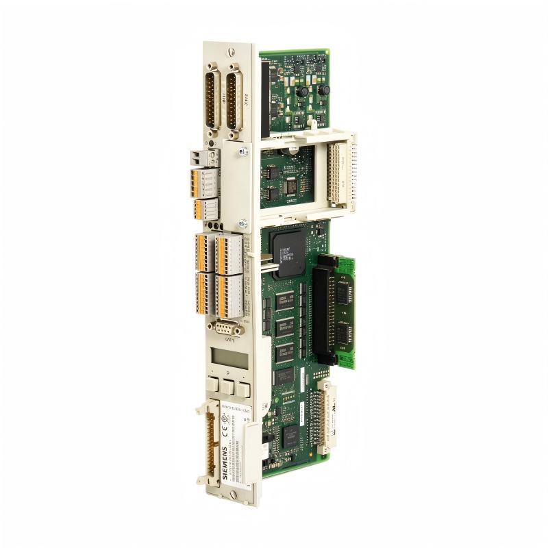
Siemens 6SN1118-0NH01-0AA1 Troubleshooting Guide: Dual-Axis Control Loop Fault Diagnosis
The Siemens 6SN1118-0NH01-0AA1 Troubleshooting Guide should begin by identifying whether the problem affects one axis or both. A fault affecting only one channel often points toward feedback, motor-side wiring, configuration, or that channel's associated hardware, while simultaneous problems on both axes can indicate a system-level issue.
6SN1118-0NH01-0AA1 Fault Diagnosis by Axis Behavior
Start with the machine's actual behavior rather than immediately replacing the module.
Typical symptoms include:
- One axis refuses to move.
- One axis oscillates around the commanded position.
- Actual speed differs from commanded speed.
- Both axes generate control-loop faults.
- An axis becomes unstable only at higher speed.
- Faults appear after the machine has warmed up.
- The machine operates normally after a cold restart.
The first question should be:
Does the fault follow the axis, the feedback circuit, or the control-loop channel?
That distinction can dramatically reduce troubleshooting time.
Siemens 6SN1118-0NH01-0AA1 No-Movement Troubleshooting
If one axis does not move, verify the basic command path first.
Check:
- CNC enable
- Axis enable
- Drive-ready condition
- Control interlocks
- Speed or position command
- Motor power section
- Feedback availability
- Axis configuration
If the controller commands movement but the drive remains disabled, investigate the enable chain before assuming that the 6SN1118-0NH01-0AA1 itself has failed.
A control-loop module cannot generate normal motor movement if the associated power section is inhibited.
6SN1118-0NH01-0AA1 Feedback Fault Diagnosis
Feedback problems are among the most important areas to investigate when an axis hunts, oscillates, or reports implausible actual speed.
A typical diagnostic sequence is:
Controller command → control-loop response → motor → feedback device → feedback cable → controller
Suppose an axis is commanded to 800 rpm, but the diagnostic display repeatedly shows 650 rpm, 920 rpm, 710 rpm, and 860 rpm.
Before changing gain parameters, inspect the feedback signal.
Check:
- Connector contacts
- Cable continuity
- Shielding
- Grounding
- Encoder/tachometer condition
- Feedback scaling
- Axis assignment
If the feedback is unstable, regulator tuning will not solve the underlying problem.
Siemens 6SN1118-0NH01-0AA1 Axis Oscillation Troubleshooting
An axis that oscillates around its commanded position can have several causes.
Possible sources include:
- Unstable feedback
- Incorrect control parameters
- Mechanical backlash
- Excessive mechanical compliance
- Incorrect motor data
- Poor grounding
- Damaged feedback cable
- Control-loop hardware problems
A useful field-style measurement might show a commanded position of 100.000 mm while the actual position continuously moves between approximately 99.96 and 100.05 mm.
If the oscillation occurs only with the motor enabled and disappears when the feedback circuit is tested independently, the feedback/control-loop path deserves closer attention.
Do not immediately increase or decrease control gains without establishing whether the mechanical system and feedback are healthy.
6SN1118-0NH01-0AA1 Overcurrent Fault Diagnosis
If an axis trips on excessive current during acceleration, compare the current requirement with the machine's normal operating baseline.
For example:
- Normal acceleration current: approximately 6.5 A
- Fault acceleration current: approximately 11.8 A
- Commanded speed: unchanged
- Mechanical load: apparently unchanged
Check for mechanical resistance, coupling problems, motor issues, incorrect motor data, and acceleration settings.
If the current rises sharply while actual speed fails to increase, the motor may be working against abnormal mechanical resistance.
If current rises while feedback reports incorrect speed, the feedback path should also be investigated.
6SN1118-0NH01-0AA1 Troubleshooting When Both Axes Fail
If both axes suddenly develop similar faults, do not start by replacing the dual-axis module.
A common-mode problem is more likely.
Inspect:
- Control power
- System bus connections
- Common enable signals
- CNC communication
- Power-section status
- Cabinet grounding
- Common feedback supply
- Configuration data
For example, if both axes simultaneously lose their actual-value information, a shared system connection or supply should be investigated before assuming that two independent feedback devices failed at exactly the same time.
Thermal Fault Diagnosis on 6SN1118-0NH01-0AA1 Systems
A machine that runs correctly for several minutes and then begins generating faults should be evaluated differently from one that fails immediately after startup.
Record the time from cold start to failure.
For example:
| Condition | Normal | Fault Condition |
|---|---|---|
| Operating time | — | 38 min |
| Cabinet temperature | 29°C | 43°C |
| Axis current | 3.5 A | 3.7 A |
| Feedback | Stable | Intermittent |
| Axis response | Normal | Unstable |
If current remains nearly unchanged while the feedback becomes unstable as cabinet temperature increases, inspect ventilation, connectors, and temperature-sensitive electronic or cable faults.
Siemens 6SN1118-0NH01-0AA1 Intermittent Fault Repair Strategy
Intermittent problems require trend information.
Record:
- Axis number
- Fault code
- Machine position
- Motor speed
- Motor current
- Actual feedback
- Cabinet temperature
- Operating time
- Whether the fault occurs during acceleration, constant speed, or deceleration
A fault that occurs only above a particular speed may indicate a feedback or mechanical resonance issue.
A fault that appears only after thermal stabilization may indicate a temperature-related connection or electronic problem.
A fault that affects both axes simultaneously should be investigated as a system-level event.
When Should the 6SN1118-0NH01-0AA1 Be Replaced?
Replacement should normally come after the external system has been checked.
A logical diagnostic order is:
Power and enable → system interconnection → motor/power section → feedback → configuration → mechanical system → control-loop module
If the same channel repeatedly fails after the motor, feedback, wiring, configuration, and associated power hardware have been verified, the 6SN1118-0NH01-0AA1 becomes a stronger candidate for hardware-level inspection or replacement.
When replacing a legacy SIMODRIVE module, preserve the existing configuration information before removing the original hardware. Incorrect axis parameters after replacement can create a second problem that looks like a hardware fault.
Siemens 6SN1118-0NH01-0AA1 Technical FAQ
1. What is the Siemens 6SN1118-0NH01-0AA1?
It is a SIMODRIVE 611 dual-axis control loop module used for controlling two drive axes.
2. Is the 6SN1118-0NH01-0AA1 a PLC CPU?
No. It is a drive control-loop module and forms part of the SIMODRIVE drive system rather than functioning as a standalone PLC CPU.
3. How many axes does the module control?
The module is designed as a dual-axis control-loop module, providing control-loop functionality for two axes.
4. What systems use the 6SN1118-0NH01-0AA1?
It is associated with Siemens SIMODRIVE 611 modular drive systems, particularly in CNC and machine-tool applications.
5. Why is feedback important during commissioning?
The control system relies on actual motor/axis feedback to regulate movement. Incorrect or unstable feedback can cause speed fluctuation, position errors, or control-loop faults.
6. What should be checked if only one axis has a problem?
Start with that axis's feedback wiring, motor, power section, configuration, mechanical load, and associated control-loop channel. Comparing it with the healthy axis is especially useful.
7. Why should feedback cables be separated from power wiring?
High-current motor and power conductors can introduce electrical interference into low-level feedback signals, potentially causing unstable actual-value readings.
8. What can cause an axis to oscillate?
Possible causes include unstable feedback, incorrect control parameters, mechanical resonance, backlash, motor problems, wiring faults, or control-loop hardware issues.
9. Why can both axes fail at the same time?
A simultaneous failure often suggests a common system condition such as control power, enable logic, system interconnection, grounding, or configuration rather than two independent axis faults.
10. What is the recommended approach to repairing the 6SN1118-0NH01-0AA1?
First isolate the fault between the controller, system interconnections, motor/power section, feedback circuit, configuration, and mechanical system. Only after these areas are verified should the dual-axis control-loop module itself be considered for repair or replacement.