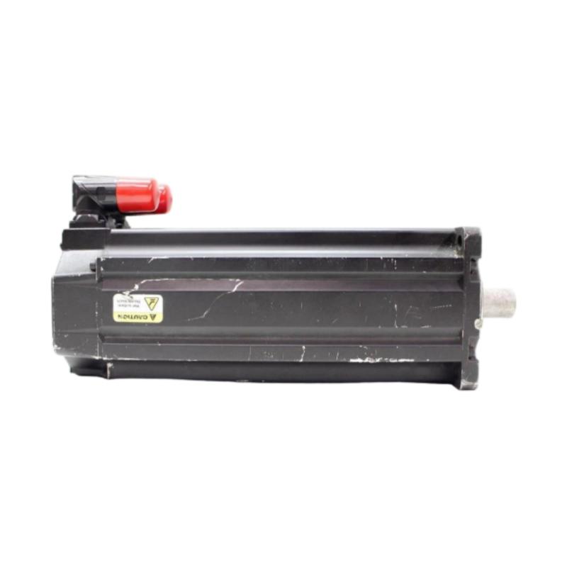
Allen Bradley MPL-B4560F-MK74AA Servo Motor Troubleshooting Guide for Fault Diagnosis and Repair
Diagnosing Allen Bradley MPL-B4560F-MK74AA Servo Motor Motion Faults
Allen Bradley MPL-B4560F-MK74AA Servo Motor troubleshooting should begin by identifying when the fault occurs and which part of the motion system is affected. A motor that fails to enable, an axis that loses position during acceleration, and a motor that vibrates at a fixed speed may have very different causes.
The first step is to capture the drive alarm, controller status, axis command, actual feedback, and operating conditions before resetting the fault. Repeated resets without recording diagnostic information can erase useful evidence and make intermittent problems harder to locate.
Common fault categories include:
Servo enable or configuration problems
Feedback communication faults
Excessive following error
Overcurrent during acceleration
Mechanical vibration or binding
Intermittent cable or connector problems
Always use the applicable drive documentation to interpret alarm codes and follow safe isolation procedures before inspecting wiring or mechanical components.
When the Allen Bradley MPL-B4560F-MK74AA Servo Motor Will Not Enable
If the servo motor does not enable, do not assume that the motor has failed. The enable sequence may be blocked by a controller interlock, safety condition, feedback fault, or incompatible drive configuration.
Check the system in this order:
Read the active drive and controller faults.
Confirm that the safety circuit and required interlocks are satisfied.
Verify that the drive is ready and receiving the enable command.
Check motor identification and feedback configuration.
Inspect the power and feedback connections after safely isolating the equipment.
Clear the root cause and repeat the enable sequence according to the manufacturer's procedure.
Field diagnostic example: An axis may remain disabled even though the drive display is powered and the network connection is active. If the controller's enable request is present but the drive reports a feedback-related fault, focus on the feedback circuit and configuration rather than replacing the motor.
Allen Bradley MPL-B4560F-MK74AA Following Error Troubleshooting
Following error occurs when the difference between commanded and actual position exceeds the configured limit. The cause may be an aggressive motion profile, excessive mechanical load, insufficient tuning, or a feedback problem.
Review the following data together:
Diagnostic Signal | Interpretation |
|---|---|
Command position | What the controller requests |
Actual position | What the feedback system reports |
Following error | Difference between command and actual position |
Motor current or torque demand | Indicates effort required to move the load |
Fault timing | Shows whether the issue occurs at startup, acceleration, or steady motion |
If following error increases mainly during acceleration, inspect load inertia, friction, and acceleration settings. If the error changes erratically while the mechanical load remains stable, investigate feedback wiring and signal integrity.
A practical diagnostic case involves a conveyor axis that faults only when loaded. If unloaded movement is smooth but the error rises as product accumulates on the conveyor, compare the actual load with the original motion-system sizing assumptions before modifying tuning parameters.
Investigating Overcurrent Faults on the Allen Bradley MPL-B4560F-MK74AA
An overcurrent fault may result from excessive mechanical resistance, a short circuit, incorrect wiring, an unsuitable motion profile, or a drive-related issue. The alarm alone does not identify which component is responsible.
Start by recording whether the fault occurs:
Immediately when the drive is enabled
At the start of acceleration
During constant-speed operation
When the mechanism reaches a particular position
During deceleration or direction reversal
A fault occurring immediately at startup suggests a different diagnostic path from one that appears only when the load moves.
For example, if an axis repeatedly trips when passing the same machine position, inspect for mechanical binding, a damaged transmission component, or an obstruction. If the fault occurs at every enable attempt, investigate electrical connections, drive configuration, and the manufacturer's prescribed motor and cable tests.
Never disconnect motor cables or perform resistance and insulation tests on energized equipment. Follow the drive manufacturer's isolation procedure and ensure that test methods are appropriate for the connected electronics.
Allen Bradley MPL-B4560F-MK74AA Feedback Fault and Position Instability
Feedback-related faults can cause the servo to stop, report incorrect position, or lose synchronization with the controller. Potential causes include a loose connector, cable damage, electrical interference, or incorrect feedback configuration.
A structured check should include:
Reviewing the exact feedback-related alarm
Inspecting connector locking and cable strain relief
Checking for damage near moving cable carriers
Verifying shielding and grounding practices
Confirming the feedback configuration in the drive
Testing with manufacturer-approved procedures
Field case: A machine may run correctly at low speed but stop intermittently during faster movement. If the fault correlates with cable-carrier movement, inspect the cable along its full travel path. A conductor can be damaged internally even when the outer insulation looks intact.
After any cable repair or replacement, repeat the motion test across the complete travel range and verify that the fault does not recur under the conditions that originally triggered it.
Diagnosing Vibration in the Allen Bradley MPL-B4560F-MK74AA Servo Motor System
Vibration can originate from servo tuning, mechanical resonance, shaft misalignment, loose mounting hardware, or load imbalance. The timing and pattern of vibration help narrow the diagnosis.
Observed Behavior | Initial Investigation |
|---|---|
Oscillation after reaching a target | Tuning, settling response, or resonance |
Vibration that increases with speed | Coupling, balance, alignment, or resonance |
Vibration during acceleration only | Inertia mismatch or aggressive motion profile |
Vibration at a repeated machine position | Mechanical binding or localized damage |
Irregular vibration with feedback alarms | Cable, connector, or feedback integrity |
Do not attempt to solve every vibration problem by changing servo gains. Excessive gain changes can make the system unstable or mask an underlying mechanical defect.
Where appropriate, compare vibration measurements at the same machine location and operating condition before and after corrective work. Consistent measurement conditions make the results more useful than subjective observations alone.
Allen Bradley MPL-B4560F-MK74AA Intermittent Faults During Production
Intermittent faults are often difficult to diagnose because the system may operate normally after a reset. The most useful evidence is the relationship between the fault and the machine's operating state.
Record:
Fault timestamp and alarm history
Axis speed and acceleration
Load condition
Actual and commanded position
Drive current or torque demand
Temperature and surrounding conditions
Whether cable movement or vibration coincides with the fault
For example, if a servo trips only after several hours of production, investigate whether the event correlates with temperature, repeated cable flexing, or changes in mechanical load. If the fault occurs immediately after a product changeover, verify that the new motion profile and load parameters are appropriate.
Change one variable at a time where practical. This preserves the ability to determine which correction actually resolves the problem.
When to Repair or Replace the Allen Bradley MPL-B4560F-MK74AA Servo Motor
Motor replacement should follow evidence-based diagnosis. Before condemning the Allen Bradley MPL-B4560F-MK74AA, check the drive, feedback circuit, cable assembly, mechanical load, and configuration.
Escalate to qualified service personnel when testing indicates a possible internal motor fault, insulation problem, bearing damage, or feedback-device failure. Use only approved testing methods and compatible replacement components.
If a replacement motor is installed, verify its exact catalog number and compatibility with the drive and existing feedback and power cables. Recheck the motor configuration, rotation direction, tuning, and safety functions before returning the machine to automatic operation.
Verifying the Allen Bradley MPL-B4560F-MK74AA Servo Motor Repair
A successful repair must eliminate the original fault under the conditions that caused it. Clearing an alarm is not sufficient proof that the system is reliable.
Complete these checks before returning the equipment to production:
Confirm that the original fault no longer appears.
Repeat the motion or load condition that triggered the problem.
Verify positioning performance and following error.
Monitor drive status and current or torque demand.
Inspect the repaired cable, connector, or mechanical interface.
Record the root cause and final corrective action.
For intermittent faults, perform enough cycles to cover the relevant operating conditions rather than relying on a single successful test.
Allen Bradley MPL-B4560F-MK74AA Servo Motor Troubleshooting Best Practices
Effective Troubleshooting combines alarm analysis, electrical inspection, feedback verification, mechanical evaluation, and controlled motion testing. The key is to separate symptoms from root causes and avoid replacing the servo motor before the surrounding system has been checked.
For the Allen Bradley MPL-B4560F-MK74AA Servo Motor, a repeatable Fault Diagnosis process can reduce unnecessary downtime, protect connected equipment, and help maintenance teams return the motion system to stable operation.