Foxboro FBM231 P0926GV Communication Module Installation Guide: Wiring, Setup and Commissioning
Foxboro FBM231 P0926GV Communication Module installation requires correct serial wiring, redundant communication configuration, field device addressing, and Foxboro DCS System Configuration. In real industrial projects, most FBM231 communication problems are caused by incorrect communication parameters, RS-485 wiring mistakes, grounding issues, or configuration mismatch instead of module hardware failure.
Foxboro FBM231 P0926GV Communication Module Application
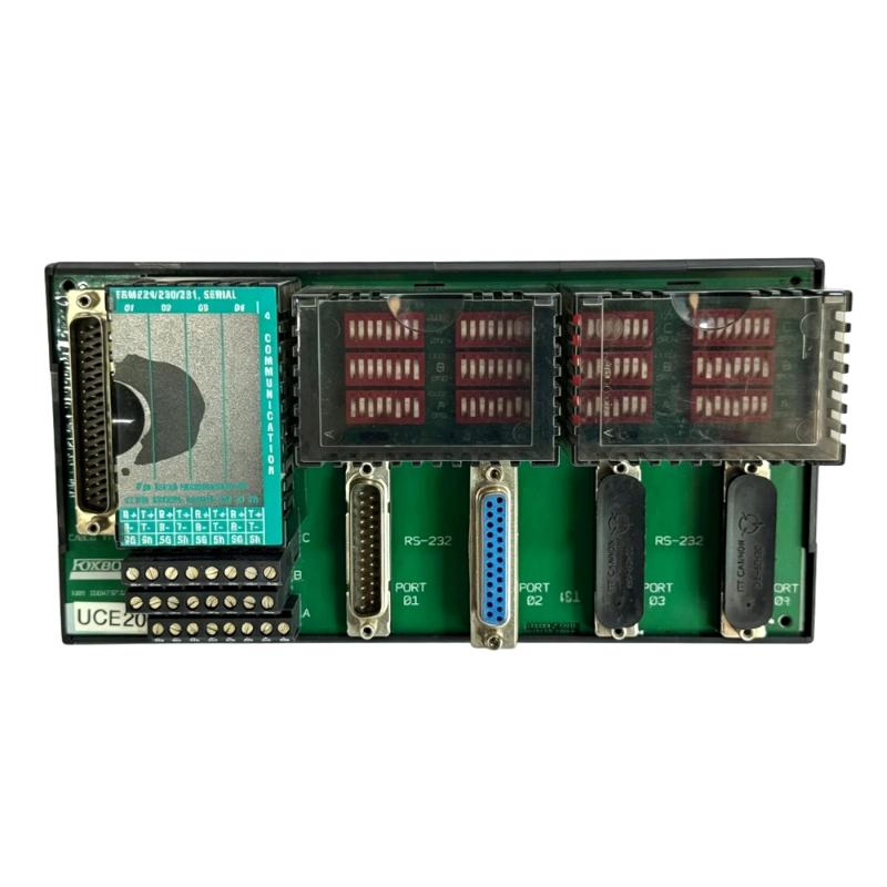
The Foxboro FBM231 P0926GV is an isolated redundant communication module designed for integrating serial field devices into Foxboro DCS systems. It is commonly used in process industries where reliable communication between intelligent instruments and the control system is required.
The module provides communication channels for connecting devices such as:
- Smart transmitters
- Serial analyzers
- Flow computers
- Intelligent instruments
- Remote monitoring equipment
- Third-party serial devices
- Modbus communication devices
The working communication path is:
Field Device → Serial Communication Network → FBM231 P0926GV → Foxboro DCS Controller → Operator Station
Unlike an analog input Module, the FBM231 does not directly convert electrical process signals. Its primary function is reliable digital data communication between field equipment and the DCS platform.
Foxboro FBM231 P0926GV Communication Module Technical Specifications
Before installation, verify the main hardware characteristics.
| Parameter | Specification |
|---|---|
| Manufacturer | Foxboro |
| Model | FBM231 P0926GV |
| Product Type | Isolated Redundant Communication Module |
| Application | Foxboro DCS Communication |
| Communication Interface | Serial Communication |
| Communication Ports | 4 Channels |
| Supported Communication Mode | RS-232 / RS-422 / RS-485 |
| Mounting Type | Modular Baseplate |
| Power Supply | 24 V DC |
| Installation Environment | Industrial Process Control |
The isolated design helps reduce the influence of electrical noise between field devices and the control system, which is especially important in chemical plants, power plants, and continuous process applications.
Foxboro FBM231 P0926GV Installation Preparation
Before installing the FBM231 communication module, engineers should confirm the complete control architecture.
The preparation checklist includes:
- Confirm Foxboro DCS compatibility
- Check baseplate installation position
- Verify redundant power supply
- Confirm field device communication protocol
- Prepare suitable serial cables
- Verify grounding arrangement
- Check cabinet environmental conditions
Before mounting the module, inspect:
- Module housing
- Connector pins
- Terminal assemblies
- Mechanical locking parts
- Signs of corrosion or damage
A common mistake during field installation is assuming a communication module failure before checking the connected serial network.
The correct engineering approach is:
Module → Wiring → Communication Parameters → Field Device → DCS Database
Foxboro FBM231 P0926GV Communication Module Wiring Installation
Correct wiring is the foundation of reliable communication.
The typical connection structure is:
FBM231 Port → Terminal Assembly → Serial Cable → Field Device
During wiring installation, check:
- RS-232 signal direction
- RS-422 differential pair connection
- RS-485 A/B polarity
- Cable shielding
- Signal grounding
- Cable length
- Terminal tightness
For RS-485 applications, incorrect polarity is one of the most common field problems.
A reversed communication pair can cause a healthy instrument to appear offline.
Before commissioning, use a wiring checklist instead of relying only on software diagnostics.
Foxboro FBM231 P0926GV Serial Communication Setup
The Setup process depends on the connected field device type.
The engineer must configure:
- Communication protocol
- Baud rate
- Data bits
- Stop bits
- Parity
- Device address
- Communication channel assignment
- Redundancy parameters
For example:
Field Device:
- Baud rate: 9600
- Data bits: 8
- Parity: Even
FBM231 Configuration:
- Baud rate: 19200
- Data bits: 8
- Parity: None
The physical connection may appear normal, but communication will fail because both sides are using different communication rules.
Correct parameter matching is essential for successful Setup.
Foxboro FBM231 P0926GV System Configuration
The System Configuration determines how the DCS identifies and exchanges data with connected devices.
Important configuration items include:
- Module address
- Communication channel mapping
- Device identification
- Protocol selection
- Data point assignment
- Alarm configuration
- Diagnostic settings
A field instrument can be powered and physically connected while still showing no data in the DCS because the software configuration does not match the actual hardware.
During commissioning, always compare:
Engineering Database → FBM231 Configuration → Field Device Settings
Foxboro FBM231 P0926GV Redundant Communication Commissioning
The FBM231 is commonly applied in systems where communication reliability is important.
During Commissioning, verify:
- Module power status
- Communication channel status
- Field device response
- DCS data refresh
- Redundant communication switching
A practical commissioning sequence:
Hardware Check → Wiring Verification → Communication Setup → Device Test → Redundancy Test → Process Validation
Redundancy should be tested under controlled conditions to confirm that communication remains available during a module or communication-path interruption.
Foxboro FBM231 P0926GV Field Commissioning Case
During one process plant commissioning project, several intelligent instruments connected through serial communication failed to appear in the Foxboro DCS.
The first assumption was that the FBM231 communication module was defective.
The engineer checked the communication chain:
Field Instrument → Serial Cable → FBM231 Channel → DCS Controller
The module diagnostic information showed normal operation.
Further testing found:
- Field device baud rate: 9600
- FBM231 channel setting: 19200
After correcting the communication parameters, all devices returned online.
The FBM231 module was not faulty. The problem was caused by configuration mismatch.
This type of fault is common in industrial communication systems because software configuration errors often look like hardware failures.
Foxboro FBM231 P0926GV Industrial Environment Installation
Although the FBM231 is designed for industrial applications, installation conditions still affect communication stability.
Pay attention to:
- Cabinet temperature
- Humidity
- Dust contamination
- Electrical noise
- Vibration
- Power quality
Serial communication cables should be separated from:
- Motor power cables
- Inverter output cables
- High-current conductors
Good cabinet layout reduces communication errors and improves long-term system reliability.
Foxboro FBM231 P0926GV Installation Troubleshooting
| Problem | Initial Diagnostic Area |
|---|---|
| Device offline | Communication parameters and wiring |
| Random communication loss | Shielding and interference |
| All devices unavailable | Module power and configuration |
| One device unavailable | Device address and cable |
| Data not updating | DCS configuration |
| Redundancy problem | Module synchronization |