Allen-Bradley 5094-RTB3I Flex 5000 Isolated Removable Terminal Block Troubleshooting Guide (Fault Diagnosis)
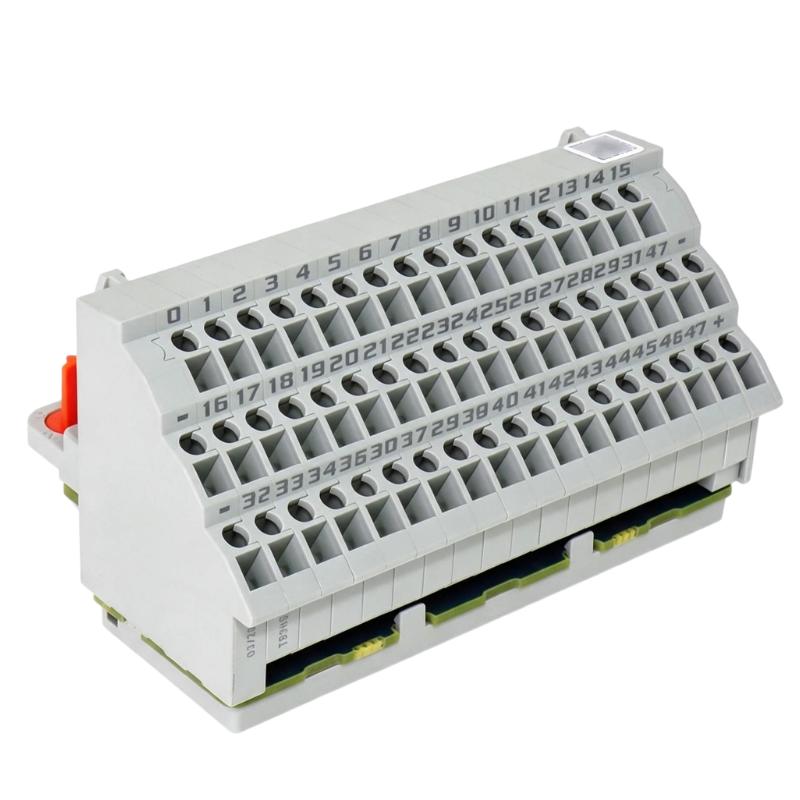
Allen-Bradley 5094-RTB3I isolated removable terminal block faults are commonly caused by incorrect field wiring, grounding problems, loose connections, signal interference, or configuration errors rather than physical terminal block damage. Troubleshooting should focus on the complete signal path from the field instrument to the PLC application.
This article describes a field case where analog process signals became unstable after a Flex 5000 I/O cabinet modification.
Allen-Bradley 5094-RTB3I Terminal Block Fault Symptoms
Typical fault symptoms include:
- Analog values jump unexpectedly
- Sensor readings become unstable
- PLC receives incorrect process data
- Channel diagnostics show abnormal status
- Machine control becomes inconsistent
Field case:
A production facility upgraded its remote I/O cabinet and installed a Flex 5000 isolated I/O system using the Allen-Bradley 5094-RTB3I terminal block.
After startup:
- PLC communication: Normal
- Field instruments: Operating
- Process values: Fluctuating
Initial assumptions:
- Sensor transmitter failure
- I/O module problem
- Network communication issue
Engineers started troubleshooting from the signal transmission path.
Allen-Bradley 5094-RTB3I Fault Diagnosis Process and Signal Analysis
Diagnostic path:
Field Instrument||5094-RTB3I Isolated Terminal Block||Flex 5000 I/O Module||PLC Controller
Engineers checked:
- Field signal output
- Terminal connections
- Channel configuration
- PLC data values
Diagnostic results:
- Field transmitter output: Normal
- Module status: Normal
- PLC reading: Incorrect
The fault was narrowed down to the connection and signal interface section.
Allen-Bradley 5094-RTB3I Signal Instability Investigation
Field measurements:
Before repair:
- Transmitter output: 12.0 mA stable
- PLC reading: 10.8–12.5 mA fluctuation
- Process value: Unstable
Engineers analyzed:
- Terminal wiring
- Shield grounding
- Isolation path
- External interference
The investigation found:
- Field cable shielding was connected incorrectly
- Electrical noise entered the measurement circuit
The 5094-RTB3I terminal interface was functioning normally, but the installation method affected signal quality.
Allen-Bradley 5094-RTB3I Root Cause Analysis and Recovery
The final root cause was improper signal grounding.
Original condition:
- Field device operated correctly
- Signal transmission was stable
Fault condition:
- Incorrect shield connection introduced noise
- PLC received unstable measurement data
Engineering conclusion:
The problem was caused by field installation practices, not terminal block failure.
Allen-Bradley 5094-RTB3I Troubleshooting Repair and System Recovery
Corrective actions:
Wiring Improvement
Performed:
- Corrected shield grounding method
- Verified terminal connections
- Checked signal polarity
System Verification
Tested:
- Field instrument output
- I/O channel response
- PLC process values
Final results:
Before repair:
- Incorrect process readings
- Control adjustments required
After repair:
- Stable analog signals
- Accurate monitoring
- Normal automation operation restored
Allen-Bradley 5094-RTB3I Common Fault Patterns and Diagnostic Methods
Signal Fluctuation Fault
Symptoms:
- Process values change randomly
Diagnosis:
- Check shielding
- Inspect grounding
- Verify terminal connections
Channel Data Incorrect
Symptoms:
- PLC value differs from field measurement
Diagnosis:
- Confirm terminal assignment
- Check signal polarity
- Verify module configuration
Intermittent I/O Fault
Symptoms:
- Signal disappears temporarily
Diagnosis:
- Inspect removable terminal seating
- Check wire tightening
- Verify field cable condition
Allen-Bradley 5094-RTB3I Long-Term Maintenance Strategy
For reliable Flex 5000 isolated I/O operation:
- Inspect terminal connections regularly
- Maintain updated wiring documentation
- Verify grounding practices
- Monitor signal quality
- Keep spare terminal blocks correctly stored
A practical engineering rule:
“When troubleshooting an Allen-Bradley 5094-RTB3I isolated removable terminal block fault, verify wiring, grounding, and signal conditions before replacing hardware.”
Recommended troubleshooting sequence:
Field signal measurement → Terminal inspection → Isolation check → Configuration verification → Wiring correction → Final system validation.