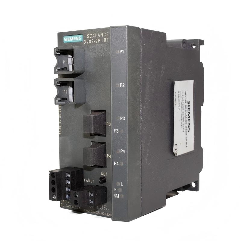
Siemens 6AG1202-2BH00-2BA3 Digital Output Module Installation Guide: Wiring and Commissioning Setup
Siemens 6AG1202-2BH00-2BA3 Digital Output Module installation requires correct terminal wiring, power supply verification, PLC hardware configuration, and output signal testing. In industrial automation systems, most digital output problems are caused by incorrect wiring, load compatibility issues, or configuration errors rather than failure of the PLC module itself.
Siemens 6AG1202-2BH00-2BA3 Digital Output Module Application
The Siemens 6AG1202-2BH00-2BA3 is a SIPLUS digital output module designed for industrial control applications where reliable switching of actuators and field devices is required.
As a Digital Output Module, it receives control commands from the PLC Controller and converts logic signals into electrical switching outputs for external devices.
Typical applications include:
- Solenoid valve control
- Motor contactor switching
- Indicator lamp control
- Relay interface control
- Machine automation systems
- Process control equipment
- Production line actuator management
The basic signal path is:
PLC Controller → Digital Output Module → Field Wiring → Actuator
Unlike analog modules that process continuous signals, a digital output module provides ON/OFF switching control for connected devices.
Siemens 6AG1202-2BH00-2BA3 Digital Output Module Technical Specifications
Before installation, verify the module parameters and application requirements.
| Parameter | Specification |
|---|---|
| Manufacturer | Siemens |
| Model | 6AG1202-2BH00-2BA3 |
| Product Type | Digital Output Module |
| Product Family | SIPLUS S7-1200 |
| Output Type | Digital Output |
| Output Channels | 16 Digital Outputs |
| Output Voltage | 24 V DC |
| Output Current | Application dependent |
| Installation Type | S7-1200 Expansion Module |
| Application | Industrial PLC Control Systems |
The module is designed for harsh industrial environments where temperature resistance and operational reliability are important.
Siemens 6AG1202-2BH00-2BA3 Digital Output Module Installation Preparation
Before installing the Digital Output Module, confirm the complete PLC system structure.
Check:
- S7-1200 PLC Controller compatibility
- CPU firmware compatibility
- Expansion position
- 24 V DC power supply condition
- Field device electrical requirements
- Output load specifications
Inspect the module before installation:
- Housing condition
- Connector terminals
- Mounting interface
- Product label information
- Signs of physical damage
A common field mistake is connecting external loads before confirming the output type and current requirements.
The correct engineering approach is:
PLC Hardware → Module Installation → Wiring → Configuration → Output Test
Siemens 6AG1202-2BH00-2BA3 Digital Output Module Wiring Installation
Correct wiring is essential for stable digital output operation.
The typical connection structure is:
24 V DC Supply → Digital Output Module → External Load → 0 V Return
During wiring, verify:
- Output terminal assignment
- Positive and negative polarity
- Load voltage rating
- Common terminal connection
- Cable size
- Grounding arrangement
Before connecting actuators, measure the field device electrical characteristics.
Incorrect wiring may cause:
- Output channel overload
- False fault signals
- Actuator malfunction
- Module damage
Siemens 6AG1202-2BH00-2BA3 PLC Hardware Configuration Setup
The Setup process requires correct configuration inside the PLC engineering environment.
The engineer should verify:
- Correct module selection
- Module address assignment
- Output channel mapping
- PLC program addressing
- Diagnostic settings
The configuration workflow is:
Hardware Installation → Module Recognition → Address Assignment → Program Download → Output Verification
If the physical module and PLC configuration do not match, the CPU may generate diagnostic alarms or the output signals may not operate correctly.
Siemens 6AG1202-2BH00-2BA3 Digital Output Commissioning Procedure
During Commissioning, test each output channel systematically.
Recommended checks:
| Test Item | Verification |
|---|---|
| Module recognition | PLC detects module correctly |
| Output LED status | Matches PLC command |
| Voltage measurement | Correct output voltage |
| Load operation | Actuator responds correctly |
| Diagnostic status | No hardware fault |
A practical commissioning method is to test outputs without the complete machine sequence first.
For example:
- Force one output channel.
- Measure the output voltage.
- Confirm actuator response.
- Repeat for remaining channels.
This method helps separate PLC logic problems from hardware wiring problems.
Siemens 6AG1202-2BH00-2BA3 System Configuration Considerations
Reliable operation depends on correct System Configuration.
Important configuration points include:
- PLC CPU settings
- Module address mapping
- Output control logic
- Safety interlocks
- Field device parameters
- Diagnostic monitoring
A digital output failure does not always indicate a defective module.
The engineer should determine whether the issue exists in:
PLC Program → Output Command → Module Channel → Field Device
Siemens 6AG1202-2BH00-2BA3 Field Installation Case
During one machine commissioning project, a pneumatic valve controlled by the Siemens 6AG1202-2BH00-2BA3 output module did not operate.
The initial assumption was a damaged digital output channel.
The engineer performed a signal analysis:
- PLC output command: ON
- Module status LED: ON
- Measured output voltage: 24 V DC
- Valve response: No movement
Further inspection found that the solenoid valve common wire was incorrectly connected.
After correcting the field wiring, the valve operated normally.
The Digital Output Module was functioning correctly.
This case demonstrates why output troubleshooting must include the complete electrical path.
Siemens 6AG1202-2BH00-2BA3 Digital Output Module Maintenance Strategy
For long-term reliability, monitor:
- Output switching frequency
- Load current
- Terminal connection quality
- Cabinet temperature
- External actuator condition
Common field issues include:
- Loose terminals
- Aging relay coils
- Short circuits
- Excessive inductive loads
Regular inspection helps prevent unexpected production downtime.
Siemens 6AG1202-2BH00-2BA3 Installation Troubleshooting
| Problem | Initial Diagnostic Direction |
|---|---|
| Output does not activate | PLC logic and wiring |
| Output LED OFF | Program command or configuration |
| Output LED ON but load inactive | Field wiring or actuator |
| Module alarm | Power supply and hardware status |
| Multiple outputs fail | Common wiring or power issue |
| Random actuator behavior | Electrical interference |